6
12a342b
6
5
78
14151617
9
10
11
12
13
MODEL 7980–A–( )
MODEL 7980–2
MODEL 7980–2–EU
DISASSEMBLY/ASSEMBLY INSTRUCTIONS
NOTICE
• Never apply excessive pressure by a holding device which
may cause distortion of a part.
• Apply pressure evenly to parts which have a press fit.
• Apply even pressure to the bearing race that will be press
fitted to the mating part.
• Use correct tools and fixtures when servicing this tool.
• Don’t damage ‘‘O” rings when servicing this tool.
• Use only genuine ARO replacement parts for this tool. When
ordering, specify part number, description, tool model number
and serial number.
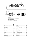
DISASSEMBLY
_ Remove hose assembly (not shown) from the inlet of the tool.
_ Insert A 1/8” diameter pin thru the hole in the housing (26), lock
sleeve (29) and spindle (28).
_ Using a wrench on flats of housing cap (32), unthread and re-
move housing cap (32) and lock sleeve (29).
_ Using a wrench on flats of nosepiece (34), unthread and re-
move from spindle, releasing collet (33).
• Models 7980–2–( ) – Place head (7) in a vise and, using a
strap type wrench, unthread and remove housing (26).
• Models 7980–A–( ) – Clamp wrench (30131) flatwise in a vise
and place slot in air inlet of tool on wrench. Using a strap type
wrench, unthread and remove housing (26).
_ Remove nozzle plate (18).
_ Insert a 1/8” diameter pin thru the hole in housing (26) and
spindle (28), and remove nut (19).
_ Press spindle (28) out nose end of housing.
_ Remove impellers (21, 22 and 24), sleeve (20), bearing (23)
and spacer (25) from housing.
_ Do not remove bearing (27) from spindle unless damage is ev-
ident. To remove, press off of spindle.
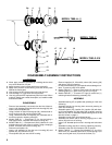
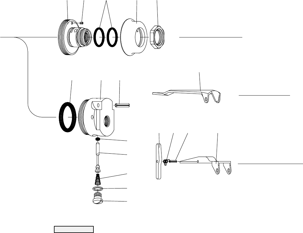
• Models 7980–2–( ) – Remove valve screw (13) and seal (12),
releasing spring (11), stem valve (10) and ‘‘O” ring (9).
• Models 7980–A–( ) – To remove ‘‘O” rings (3), remove nut (1),
releasing throttle and bushing assembly (2a).
ASSEMBLY
_ Assemble bearing (27) to spindle (28), pressing on inner race
of bearing.
_ Assemble spindle into housing theu nose end, pressing on
outer race of bearing.
_ Assemble spacer (25), impeller (24), impeller (22) with bear-
ing (23) and impeller (21) with sleeve (20) to spindle, securing
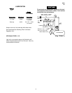
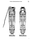
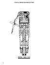
with nut (19). NOTE: Assemble impellers with grooves in the
direction shown on page 4.
_ Assemble nozzle plate (18) and head to tool.
_ Assemble lock sleeve (29) to housing, aligning hole in lock
sleeve (29) with hole in housing.
_ Insert a 1/8” diameter pin thru hole in housing and lock sleeve
(29).
_ Assemble housing cap (32) to housing, tightening securely.
_ Assemble collet (33) and nosepiece (34) to spindle.
• Models 7980–2–( ) – Grease and assemble ‘‘O” ring (9) to
stem valve (10). Assemble stem valve (10) and spring (11) to
head, securing with seal (12) and valve screw (13).


