


M12
15
6
DISASSEMBLY/ASSEMBLY INSTRUCTIONS
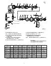
MOTOR ASSEMBLY
– Assemble wavy spring (16) to end plate and assemble end
plate to rotor (19).
– Lubricate bearing (15) with ARO 33153 grease.
– Press bearing (15) on rotor and into end plate (17). NOTE:
Press on inner race of bearing. Assemble with shielded side
out. Outside face of inner race must be flush with end of ro-
tor.
– Assemble washer (14) and screw (13) to rotor using a good
grade of thread adhesive.
– Coat rotor blades (18) with ARO 29665 spindle oil and as-
semble to rotor slots – straight side out.
– Coat i.d. of cylinder (22) with ARO 29665 spindle oil and as-
semble over rotor. NOTE: Air inlet holes in end of cylinder
must be aligned with air inlet holes in end plate (17).
– Lubricate bearing (24) with ARO 33153 grease.
– Assemble bearing (24) to end plate (23), shielded side out.
– Assemble spacer (20) and end plate (23), with bearing, to
rotor. NOTE: Press on inner race of bearing. Be sure rotor
turns without binding.
– Assemble gear (25) to rotor. Lubricate gear with ARO 33153
grease.
– Assemble motor to housing.
THROTTLE DISASSEMBLY
– Remove screw (12), washer (11), spring (10) and valve (8)
with ‘‘O” ring (9).
– Remove inlet adapter (1) and air diffuser (2).
– To remove lock nut (6), remove retaining ring (7).
– To remove lever (4), remove roll pin (3).
THROTTLE ASSEMBLY
– Lubricate and assemble ‘‘O” ring (9) to valve stem (8).
– Assemble valve stem (8) and spring (10) to head and secure
with washer (11) and screw (12).
– Assemble lock nut (6) to head. Secure with retaining ring (7).
– Assemble air diffuser (2) and inlet adapter (1) to head.
– Assemble lever (4) to head, securing with roll pin (3).
(ATP–2)
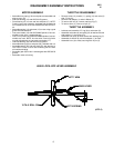
45953 LOCK–OFF LEVER ASSEMBLY
45777 ARM
45952 LEVER
Y178–5 ROLL PIN
45778 SPRING