


21
MAINTENANCE SECTION
Always wear eye protection when operating or
performing maintenance on this tool.
Always turn off air supply and disconnect air supply
hose before installing, removing or adjusting any
accessory on this tool, or before performing any
maintenance on this tool.
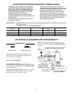
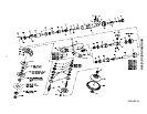
LUBRICATION
Each time a GRG Grinder, GRS Sander, or GRP Polisher
is disassembled for maintenance, repair or replacement of
parts, lubricate the tool as follows:
1. Moisten all O–rings with O–ring lubricant.
2. Coat the inner surface of the Arbor Coupling (42), the
spline of the Rotor (26) and the spline of the Bevel
Pinion (31) with 3 to 4 cc of IRAX No. 68–1LB
Grease. Do not substitute any other grease.
3. After assembling the tool, remove the Oil Chamber
Plug (7) and fill the oil chamber with IRAX
No. 50P Oil. Tighten the Plug to 3–3/4 to 7–1/2 ft–lb
(5 to 10 Nm) torque. Inject 2.5 cc of the
recommended oil into the inlet before installing the
Inlet Bushing (4).
4. Inject 5 cc of IRAX No. 68–1LB Grease into both
Grease Fittings (44).
DISASSEMBLY
General Instructions
1. Do not disassemble the tool any further than
necessary to replace or repair damaged parts.
2. Whenever grasping a tool or part in a vise, always use
leather–covered or copper–covered vise jaws to
protect the surface of the part and help prevent
distortion. This is particularly true of threaded
members and housings.
3. Do not remove any part which is a press fit in or on a
subassembly unless the removal of that part is
necessary for repairs or replacement.
4. Do not disassemble the tool unless you have a
complete set of new gaskets and O–rings for
replacement.
Disassembly of the Angle Head
For GRG15A or GRG15M Models:
1. Grasp the Angle Arbor Housing (43) in
leather–covered or copper–covered vise jaws, angle
head up.
2. Insert a 5” (127 mm) long 3/16” hex wrench into the
elongated slot in the end of the Dead Handle (70) and
loosen and remove the screw and the Dead Handle
from the Angle Arbor Housing (43).
3. Using the Autobalancer Wrench (Part No.
88V60–169) to hold the Depressed Center Wheel
Arbor (60) against rotation, proceed as follows:
a. Using a hex wrench, unscew and remove the
Wheel Retaining Screw (65).
b. For Type 27 and 28 Plain Hole Wheels, use the
Depressed Center Wheel Nut Spanner Wrench
(Part No. D32–26) to unscrew and remove the
Depressed Center Wheel Nut (67). Remove the
wheel.
For Type 27 and 28 Mounted Wheels, unscrew
the wheel.
c. For Type 27 and 28 Plain Hole Wheels, unscrew
and remove the Depressed Center Wheel Flange
(66 or 68).
For Type 27 and 28 Mounted Wheels, remove
any Depressed Center Wheel Spacers (63).
4. Slide the Autobalancer Assembly (61) off the Arbor.
5. Unscrew and remove the Wheel Guard Screws (54).
Remove the Screw Lock Washers (53) and the Wheel
Guard (59).
6. Lift the Depressed Center Wheel Arbor (60) from the
Angle Arbor Housing.
Do not remove the Mounting Plate Pin (45) unless
it is bent or broken. The Mounting Plate Pin is the
alignment pin for the Wheel Guard and must be
used to assure correct mounting of the Wheel
Guard. Use pliers to remove the Mounting Plate
Pin if removal is necessary and a new Pin is
available.
7. Remove the Angle Arbor Housing from the vise.
8. Lay the Angle Arbor Housing on a workbench, guard
side down. Lightly tap the angle arbor housing head
with a soft hammer to release the Upper Arbor
Bearing (47) and Upper Bearing Spring Washer (46).