


DISASSEMBLY/ASSEMBLY INSTRUCTIONS
•
•
•
•
l
l
•
•
•
•
•
•
Never apply excessive pressure by a holding device which
may cause distortion of a part.
Apply pressure evenly to parts which have a press fit.
Apply even pressure to the bearing race that will be press
fitted to the mating part.
Use correct tools and fixtures when servicing this tool.
Don’t damage “0” rings when servicing this tool.
Use only genuine Ingersoll-Rand replacement parts for this
tool. When ordering, specify part number, description, tool
model number and serial number.
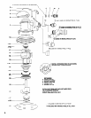
MOTOR DISASSEMBLY
Remove sanding pad (24).
Remove retaining ring (28).
Remove spindle assembly (27) (includes bearing). NOTE: Do
not attempt to remove bearing from spindle.
Remove lock ring (24) and pull motor and seal (19) from hous-
ing.
Remove retaining ring (15).
Using special brass blocks to fit around o.d. of cylinder, clamp
around cylinder and press shaft of counterbalance thru bear-
ing (16) and end plate (17).
Remove blades (21), rotor (20) and key (25).
Remove end plate (22) and bearing (16).
MOTOR ASSEMBLY
Grease and assemble “0” ring (23) to lock ring (24).
Assemble lock ring (24) over counterbalance (26).
Assemble bearing (16) into end plate (22), pressing on outer
race of bearing.
Assemble end plate (22) onto shaft of counterbalance, press-
ing on inner race of bearing.
Install key (25) in key slot.
Assemble rotor (20) to counterbalance, aligning keyway to
key (25).
Assemble five rotor blades (21) to rotor slots.
Assemble cylinder (18) over rotor, aligning roll pin in cylinder
with slot in end plate.
Assemble bearing (16) into end plate (17), pressing on outer
race of bearing.
Assemble end plate (17), with bearing (16), to counterbal-
ance, pressing on inner race of bearing. NOTE: Align slot in
end plate with roll pin in cylinder.
Install retaining ring (15) to groove in counterbalance, with
bow in ring positioned as shown on parts illustration page.
Assemble seal (19) to grooves in cylinder.
Assemble motor to housing, aligning seal (19) with air inlet.
Tighten lock ring (24), securing motor assembly.
Lubricate needle bearing, contained in counterbalance, with
IR #68 grease.
Assemble spindle assembly (27) to counterbalance, securing
with retaining ring (28).
Assemble sanding pad (29) to tool and tighten securely.
THROTTLE DISASSEMBLY
Remove vacuum adapter (12)(if applicable) by pressing in on
tabs and pulling vacuum adapter out.
Models R02( )A-VLV: Remove eductor assembly (31)(if ap-
plicable). To remove, unthread upper section, press in on tabs
of lower section and pull assembly from housing.
Remove inlet adapter (9), releasing spring (8) and valve (7).
NOTE: Do not remove seat (6) unless damage is evident.
Remove muffler (11), releasing muffler tube (10).
To remove valve stem (2), remove roll pin (4) and lever (3).
THROTTLE ASSEMBLY
Assemble valve stem (2) into housing with hole in valve stem
in line with housing to accept valve (7).
Assemble seat (6) into housing with rounded corners into
housing first.
Assemble valve (7) into housing, securing valve stem (2).
Assemble spring (8) into housing.
Assemble inlet adapter (9) to housing, securing throttle com-
ponents.
Assemble lever (3) to housing, securing with roll pin (4).
Assemble vacuum adapter (12) or plug (13) to housing. To as-
semble vacuum adapter, push into housing until tabs on vacu-
um adapter snap into slots in housing. To assemble plug, push
into housing until it is flush with port opening.
Models R02( )A-VLV: Assemble eductor assembly (31) to
housing. To assemble, insert tapered section of eductor as-
sembly into housing while aligning threaded section with
housing. Using a wrench on flats, tighten threaded section se-
curely. Tabs will snap into slots in housing.
6