


2
REGULATORY LISTING IN
COMPLIANCE WITH:
UL 544 - Listed Medical and Dental Equipment
CSA C22.2 No. 125 - Certified Medical and Dental
Equipment
ELECTRICAL
Compressor
If the overload protector shuts off the motor frequently,
you may have a low voltage situation. Low voltage can
also be suspected when:
1. The motor does not get up to full power or speed.
2. Fuses or circuit breakers activate when starting com-
pressor.
3. Lights dim or remain dim when compressor is started.
4. Other motor operated appliances fail to operate prop-
erly. Too many motor operated appliances on same
circuit.
NOTE: The motor of this compressor has a thermal over-
load protector. If the motor should overheat, the over-
load protector will shut off the motor. If this should occur,
turn the ON/OFF switch to the OFF position and allow
the motor to cool (approximately 5 minutes). Restart com-
pressor. If the compressor fails to start, wait an additional
5 minutes before attempting to restart. If this fails, check
for a blown fuse on the household electric circuits. If the
unit still does not restart, the motor must be replaced.
Call your dealer immediately.
Extension Cords
NOTE: Make certain extension cord is in good condition
and is NOT LESS than 18 gauge for 25 feet, 16 gauge
for 50 feet and 14 gauge for 100 feet.
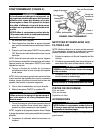
OPERATION (FIGURE 2)
WARNING
Proper operation of this product is necessary to
avoid physical harm. Improper use can cause
personal injury and/or tissue damage. This prod-
uct should not be used unless the operator has
been instructed by a physician or other qualified
health care professional.
DO NOT use the compressor for continuous op-
eration more than 10 hours, this can result in over-
heating and damage to the compressor.
1. Familiarize yourself with this unit.
2. Place unit on table and push down hard so that suc-
tion feet hold unit firmly in place.
3. Check to see that the ON/OFF switch is in the OFF
position. Plug power cord into electrical outlet.
NOTE: Before attempting to start a cold unit, let the unit
reach room temperature in a heated area, then press
the ON/OFF switch to start the unit.
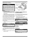
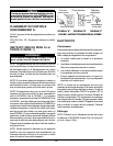
Metal
Screw
Tab for
Metal Screw
Grounded
Outlet
2-Pole
Receptacle
Temporary Adapter
Grounding
Plug
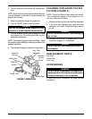
SKETCH "A" SKETCH "C"
SKETCH "B"
FIGURE 1 - GROUNDING INSTRUCTIONS
GROUNDING INSTRUCTIONS
(FIGURE 1)
WARNING
Improper use of the grounding plug can re-
sult in a risk of electric shock.
NOTE: This product should be grounded. In the event of
an electrical short circuit, grounding reduces the risk of
electrical shock by providing an escape wire for the elec-
trical current. This product is equipped with a cord hav-
ing a grounding wire with a grounding plug. The plug
must be plugged into an outlet that is properly installed
and grounded.
NOTE: If repair or replacement of the cord or plug is
necessary, do not connect the grounding wire to either
flat blade terminal. The wire with insulation having an
outer surface that is green with or without yellow strips is
the grounding wire.
NOTE: This product is for use on a nominal 120 V circuit,
and has a grounding plug that looks like the plug illustra-
tion in SKETCH A of FIGURE 1. A temporary adapter,
which looks like the adapter illustrated in SKETCHES B
and C, may be used to connect this plug to 2-pole recep-
tacle as shown in SKETCH B if a properly grounded
outlet is not available. The temporary adapter should be
used only until a properly grounded outlet (SKETCH A)
can be installed by a qualified electrician. The green col-
ored rigid ear, lug and the like extending from the adapter
must be connected to a permanent ground such as a
properly grounded outlet box cover. Whenever the
adapter is used, it must be held in place by the screw.
NOTE: Check with a qualified electrician or serviceman
if the grounding instructions are not completely under-
stood, or if in doubt as to whether the product is properly
grounded.