12
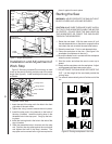
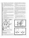
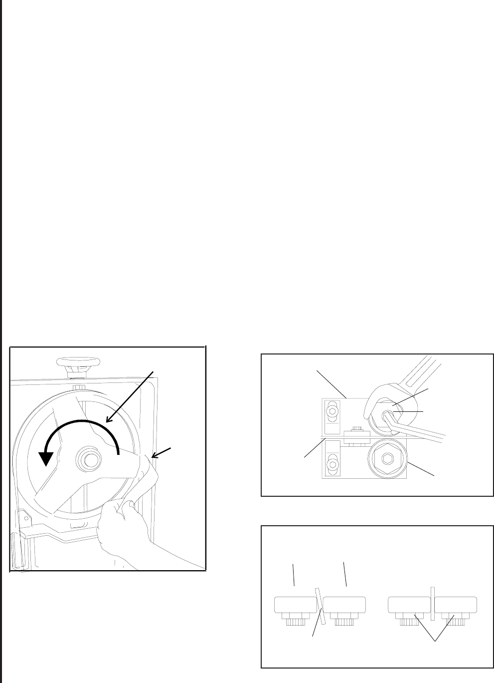
the wheel shoulder. Put a 6-inch length of paper
between the blade and the wheel as shown in figure
11. The paper should not be cut as it passes be-
tween the wheel shoulder and the blade.
9. Turn the single hex adjustment screw a small amount.
Repeat the insertion of the paper between the wheel
shoulder and the blade until the paper is cut in two
pieces.
NOTE: You may have to repeat the check with the
paper several times before the blade and the shoulder
cuts the paper into two pieces. Do not hurry the ad-
justment. Patience and accuracy here will pay off with
better, more accurate, quieter cutting and much longer
machine and blade life.
10. When the paper is cut, turn the hex adjustment
screw slightly in the counterclockwise direction. This
assures that the blade is not touching the shoulder
of the wheel.
11. Shut off the saw.
12. Hold the hex adjustment screws with a wrench and
tighten the center locking screws. Make sure the
hex adjustment screws do not move while tightening
the center screws.
13. Install the two blade guide bearing brackets. Posi-
tion the guides so the bearings just touch the blade.
14. Install the left blade guard.
15. Close the saw head cover. Tighten all four knobs.
should rarely require adjustment. When adjustment is
required, adjust immediately. Failure to maintain proper
blade adjustment may cause serious blade damage or
inaccurate cuts.
It is always better to try a new blade when cutting
performance is poor. If performance remains poor af-
ter changing the blade, make the necessary adjust-
ments.
If a new blade does not correct the problem, check
the blade guides for proper spacing. For most effi-
cient operation and maximum accuracy, provide 0.001
inch clearance between the blade and the guide bear-
ings. The bearings will still turn freely with this clear-
ance. If the clearance is incorrect, the blade may track
off the drive wheel.
CAUTION: CHECK THE BLADE TO MAKE SURE THE
WELDED SECTION IS THE SAME THICKNESS AS
THE REST OF THE BLADE. IF THE BLADE IS
THICKER AT THE WELD, THE GUIDE BEARINGS MAY
BE DAMAGED.
If required, adjust the guide bearings as follows:
1. The inner guide bearing is mounted on a concen-
tric bushing and can not be adjusted.
2. The outer guide bearing (closest to the operator) is
mounted on an eccentric bushing and can be ad-
justed.
3. Hold the bushing with a 3/4-inch wrench and loosen
Figure 13: Blade -to-bearing orientation
Figure 12: Adjustment of guide bearings
INCORRECT CORRECT
Outer
Roller
Inner
Roller
Blade
Locking
Screw
Guide Bracket
Eccentric
Bushing
Locking
Screw
Blade
Outer Roller
(Blade Guide Roller)
Figure 11: Checking blade-to-wheel clearance
using paper strips
Motor "ON"
Upper Wheel
Rotating
Put Strip
Between
Wheel
and
Blade
Blade Guide Bearing
Adjustment
Proper adjustment of the blade guide bearings is
critical to efficient operation of the cut-off saw. The
blade guide bearings are adjusted at the Factory. They


