


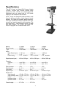
Introduction
This manual includes operating and maintenance
instructions for the JET 15-Inch Vari-Speed Drill
Presses, Models J-A3816, J-A5816, and J-A5818.
This manual also includes parts listings and
illustrations of replaceable parts.
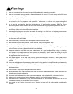
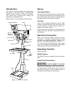
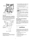
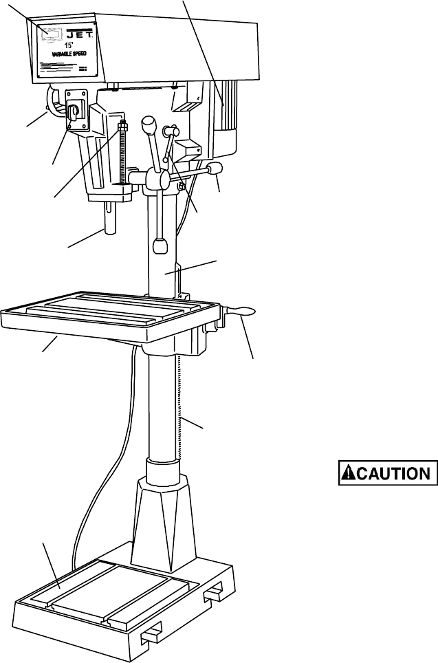
Refer to Figure 1 for key features of the drill press.
LED Speed Display
Speed
setting
Handwheel
On/Off Switch
Depth Stop
Spindle
Feed Handle
Head locking
Handle
Motor
Column
Table
height
adjustment
Rack
Work Table
Base
Figure 1 – Drill Press Features
Set-up
Securing the Base
The base of the drill press has four mounting holes.
The drill press should be level and rest solidly on the
floor. Place shims under the four mounting holes in
the base as required to level the drill press.
Cleaning
Clean off any protective grease with solvent. After
cleaning, lubricate the base, table, and column with
a light coating of medium weight machine oil.
Repeat at six months intervals.
Internal parts of the drill press are lubricated at the
factory. No further lubrication is required at the time
of installation.
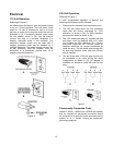
Electrical Connection
Refer to the Wiring Diagram section for wiring
information. Connection to electrical power should
be made by a qualified electrician. Observe local
electrical codes when connecting the machine.
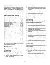
The motor should be protected with a time delay
fuse or circuit breaker with a amperage rating slightly
higher than the full load current of the motor.
Operating Controls
(Refer to Figure 2)
ON/OFF Switch
The ON/OFF switch is located at the front of the drill
head.
Speed Control Handwheel
To avoid damage to the speed
adjustment mechanism, the motor must be oper-
ating before attempting to adjust the speed rate.
The speed control handwheel is located on the left
side of the drill head. An LED speed indicator is
provided on the face plate on the drill head.