


8
Specifications: JDP-17FSE
Stock Number................................................................................................................................ 354171
Swing .............................................................................................................................................16-1/2”
Type..................................................................................................................................................Floor
Drilling Capacity ..................................................................................................................................5/8”
Chuck Size..........................................................................................................................................5/8”
Spindle Travel ..................................................................................................................................3-3/8”
Spindle Distance to Base......................................................................................................................49”
Spindle Distance to Table (max.)....................................................................................................29-1/8”
Table Size Diameter.......................................................................................................................13-3/4”
Spindle Taper ....................................................................................................................................MT-2
Column Diameter .............................................................................................................................3-1/8”
Number of Spindle Speeds....................................................................................................................12
Range of Spindle Speeds ................................................................................................. 250-3,000 RPM
Overall Height ......................................................................................................................................66”
Base Size..............................................................................................................................11” x 19-5/8”
Motor......................................................................................................................................3/4HP, 1 Ph
...........................................................................................................................115/230V, prewired 115V
Net Weight (approx.) ...................................................................................................................... 172 lb.
Shipping Weight (approx.) .............................................................................................................. 183 lb.
Table of Contents Page
Warranty .................................................................................................................................................2
Warnings..............................................................................................................................................3-4
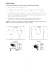
Grounding Instructions.............................................................................................................................5
115V Operation .......................................................................................................................................5
230V Operation .......................................................................................................................................6
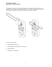
On-Off Switch Padlock ............................................................................................................................7
Specifications..........................................................................................................................................8
Table of Contents....................................................................................................................................8
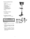
Contents of Shipping Container ...............................................................................................................9
Tools Supplied for Assembly ...................................................................................................................9
Tools Required for Assembly...................................................................................................................9
Before Assembly .....................................................................................................................................9
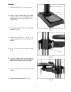
Assembly..........................................................................................................................................10-11
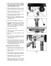
Removing the Chuck and Arbor.............................................................................................................11
Adjusting the Depth Stop .......................................................................................................................12
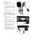
Changing Spindle Speeds......................................................................................................................12
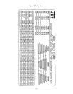
Speed and Pulley Chart.........................................................................................................................13
Return Spring Adjustment......................................................................................................................14
Table Tilt Adjustment.............................................................................................................................14
Basic Operation.....................................................................................................................................15
Lubrication.............................................................................................................................................15
Troubleshooting.....................................................................................................................................16
Part’s Breakdown...................................................................................................................................17
Part’s List..........................................................................................................................................18-19
Wiring Diagram .....................................................................................................................................20
The specifications in this manual are given as general information and are not binding. WMH TOOL
GROUP reserves the right to effect, at any time and without prior notice, changes or alterations to parts,
fittings, and accessory equipment deemed necessary for any reason whatsoever.