


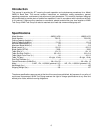
9
Assembly of JWBS-14OS
NOTE: If any of the assembly procedures need
further clarification, refer to the exploded views
in the back of this manual.
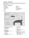
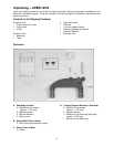
Tools Required for Assembly
Metric combination wrench set and adjustable
wrench
#1 and #2 cross point screwdrivers
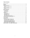
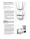
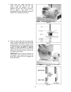
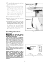
1. Place stand top upside down on a level
surface. Fasten four stand legs to stand top
using carriage bolts, washers, lock washers,
and nuts, as shown in item A on page 7.
Note: Stand legs fasten to outside of stand
top (Figure 1). Do not tighten at this time.
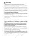
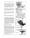
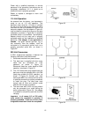
2. Fasten two long braces and two short
braces to stand legs using carriage bolts,
washers, lock washers, and nuts, as shown
in item A, page 7. Do not tighten at this time.
See Figure 2.
3. Turn assembly over and stand it on its legs.
Push down slightly on the top to make sure
the stand settles properly and all four legs
sit flat on a level surface. Tighten all nuts.
Saw body is heavy! Use
caution when lifting and stabilize until firmly
attached to the stand! Failure to comply may
cause serious injury!
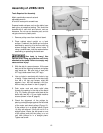
4. With the aid of a second person, lift the saw
body out of the shipping container and place
onto the stand top. Be sure front of saw
(with JET logo) faces stand front (JET logo).
See photo on cover for orientation.
5. Line up holes in saw body with holes in
stand. Place support plate to the underside
of stand as shown in the parts diagram for
the open stand assembly (item 5, page 30).
Fasten saw body, stand, and support plate
together with four hex cap screws, eight flat
washers, four lock washers, and four hex
nuts, as shown in item B on page 7.
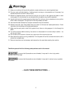
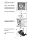
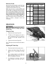
6. To mount the motor, place four rubber
grommets over holes in stand top (Figure 3).
Note: Use of rubber grommets is essential
for eliminating excessive vibration.
Figure 1
Figure 2
Figure 3