


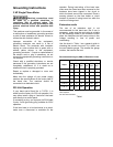
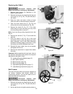
16
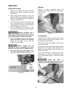
Blade Tension
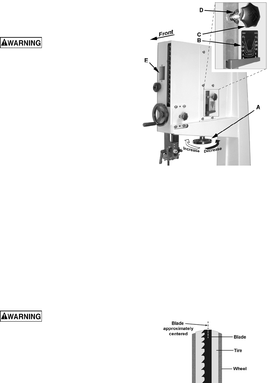
Blade tension is set with the blade tension
handwheel (A, Fig. 19) and is performed following
blade replacement and periodically as the blade
stretches from use.
Disconnect machine from
power source before making any adjustments.
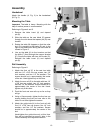
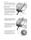
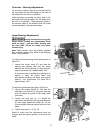
Referring to Figure 19:
1. Set the blade tension by rotating the
handwheel according to the arrow directions in
Figure 19.
2. The gauge (B) indicates the approximate
tension according to the width of the blade in
inches. Initially, set the blade tension to
correspond to the width of your blade.
The JWBS-18X and JWBS-18X-3 come with a
3/4" blade so the tension should be set at 3/4"
when using this blade.
Note: The tension gauge can also be seen
from the front of the saw through the wheel
when the upper door is open.
As you become familiar with the saw, you may find
it necessary to change the blade tension from the
initial setting.
Keep in mind that too little or too much blade
tension can cause blade breakage and/or poor
cutting performance.
Tip: When the band saw is not being used, slightly
release the tension on the blade – this will prolong
the blade’s life. Make a note of the specific tension
setting for that particular blade, as shown on the
gauge (B). The tension can then be re-set quickly
when band saw operations are resumed.
Blade Tracking
Tracking refers to the position of the saw blade on
the wheels while the machine is in operation.
Tracking has been factory-adjusted. However, it
should be checked occasionally, including after
every blade change.
Disconnect machine from
power source before making any adjustments.
Important: The blade must be properly tensioned
before adjusting blade tracking (see previous
section). Make sure the blade guides and other
parts of the machine will not interfere with the
movement of the blade.
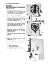
To inspect and adjust tracking, proceed as follows:
1. Open upper front door to expose the wheel.
Rotate the wheel clockwise by hand and
observe the position of the blade on the wheel
Figure 19
through the window (E, Fig. 19). The blade
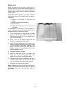
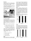
should ride upon the center of the wheel
(Figure 20).
2. If the blade tends to move toward the edge of
the wheel, loosen the wing nut (D, Fig. 19) and
slightly rotate the knob (C, Fig. 19). Rotating
the knob clockwise will cause the blade to
move toward the rear edge of the wheel.
Rotating the knob counterclockwise will cause
the blade to move toward the front edge of the
wheel.
Note: This adjustment is sensitive; perform it in
small increments and give the blade time to
react to the changes as you continue to rotate
the wheel.
3. When the blade is tracking properly in the
center of the wheel, re-tighten the wing nut
(D, Fig. 19).
4. Close the upper front door.
Figure 20