


11
Fence Adjustments
Note: Fence adjustments should be performed in
the order given.
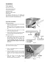
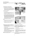
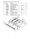
Leveling Fence to the Saw Table
1. Place the fence on the table and lock it.
2. View the fence from the left side of the saw
(Figure 14). Look for the space between the
table and the fence bottom to be equal along
the entire length of the fence (A, B, Fig. 14).
If adjustment is necessary:
3. Unlock the fence.
4. Using a 10mm wrench, loosen the lock nut that
secures the foot adjustment (C, Fig. 14)
5. Rotate the foot, retracting it such that it does
not come in contact with the back rail (Fig. 14).
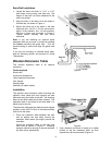
6. Raise or lower two nylon adjustment screws
(D, Fig. 15) the same number of turns until the
space between the bottom of the fence and the
table is the same. Care must be taken to raise
or lower the fence on each side equally or the
fence may not be 90° to the table after the
height adjustment is performed.
When the space at points A and B (Fig. 14) are the
same:
7. Extend the foot (C, Fig. 14) by rotating it until it
just comes in contact with the back rail.
8. Tighten the lock nut to secure the foot,
preventing it from further rotation.
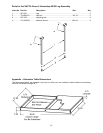
Adjusting Fence Parallel to the Miter Slot
1. Place the fence next to the outside edge of the
right miter slot and lock it.
2. The fence should be even with the miter slot
from front to back.
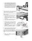
3. If the fence is not even along the length of the
miter slot, unlock the fence, remove it and turn
upside down (Figure 16).
4. Adjust one of the two setscrews (E, Fig. 16)
until the fence is even with the miter slot edge
along its entire length when locked.
Note: You may need to re-adjust the clamping
pressure after aligning the fence.
Fence Side Plate
Table Top
A
C
B
Guide Tube
Back Rail
Front Rail
Figure 14
Figure 15
Figure 16
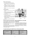
Clamping Pressure Adjustment
The XACTA Fence II has been adjusted at the
factory to lock securely when the lock handle is
pushed down. If adjustment is needed:
1. Unlock the fence.
2. Remove the fence from the guide rail.
3. Turn the fence over.
4. Adjust each of the two setscrews (E, Fig. 16)
exactly the same number of rotations until the
fence is held securely when the lock handle is
pushed down.
A clockwise rotation of the setscrews will increase
the cam pressure. Counterclockwise rotation will
decrease cam pressure.