


14 4 1/4-Inch Disc Grinder Operator's Manual
OPERATION (CONTINUED):
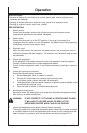
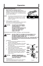
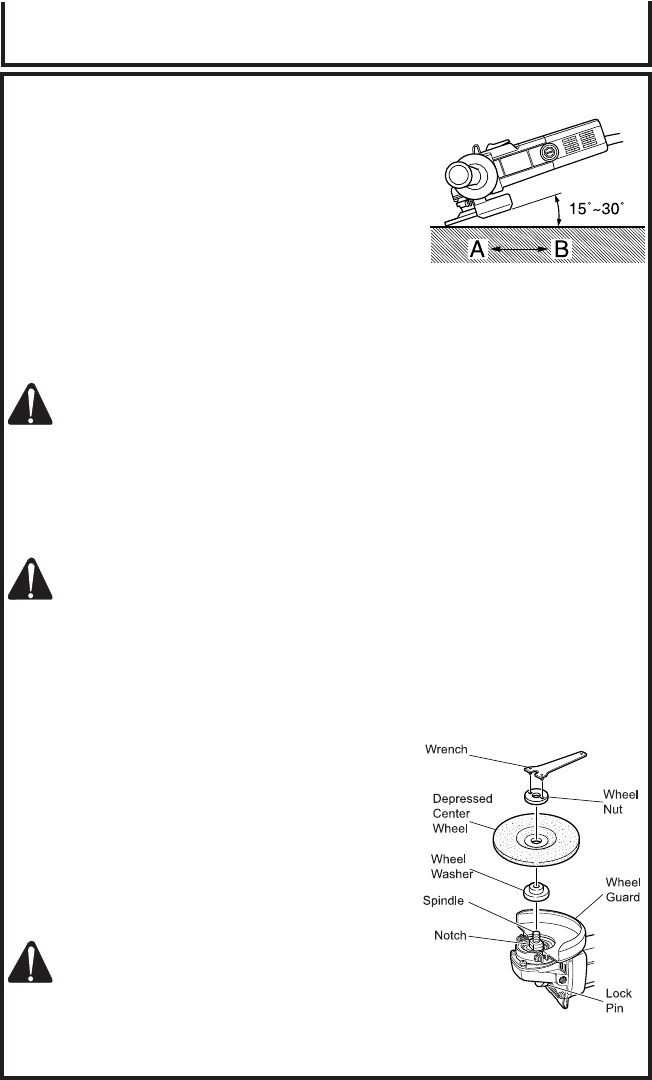
5. Move the grinder in the proper direction:
When using a new depressed center wheel in
direction A (Fig. 2), the wheel edge may cut into the
workpiece. In this case, grind in direction B (Fig. 2).
Once the wheel edge is worn, the workpiece can be
ground in both directions.
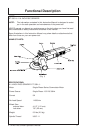
NOTE: The wheel provided (resinoid wheel) is rated as
Class A grain and # 36 grain size. It is most
suitable for heavy grinding of steel and other
types of materials.
6. Adjust operation to desired finish:
For a fine finish, decrease pressure by lifting slightly.
Grind slowly and at the appropriate speed.
CAUTION: THE REVOLVING DEPRESSED
CENTER WHEEL WILL CREATE
AIR TURBULENCE.
DO NO LAY THE GRINDER DOWN
IN AREAS OF DUST OR DIRT
UNTIL IT HAS COME TO A
COMPLETE STOP.
1. Assembling
a. Turn the disc grinder upsidedown so that the
spindle is facing upward.
b. Align the oval-shaped indentation of the wheel
washer with the notched part of the spindle,
then attach them.
c. Fit the protuberance of the depressed center
wheel onto the wheel washer.
d. Screw the wheel nut onto the spindle.
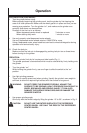
e. While pushing the lock pin with one hand, lock
the spindle by turning the depressed center
wheel slowly with the other hand. Tighten the
wheel nut by using the supplied wrench as
shown in Fig. 3.
CAUTION: TIGHTEN THE WHEEL NUT
SECURELY AND CONFIRM THAT
THE DEPRESSED CENTER WHEEL
DOES NOT WOBBLE.
2. Disassembling:
To remove the depressed center wheel, follow the
above-mentioned procedure in reverse order.
DEPRESSED CENTER WHEEL ASSEMBLY AND DISASSEMBLY:
WARNING: NEVER ATTEMPT TO ASSEMBLE OR DISASSEMBLE THE
DEPRESSED CENTER WHEEL WHILE THE GRINDER IS
CAPABLE OF BEING TURNED “ON”.
BE SURE POWER SWITCH IS IN THE “OFF” POSITION AND THE
ELECTRICAL CORD HAS BEEN DISCONNECTED FROM THE
RECEPTACLE.
Operation
(Fig. 2)
(Fig. 3)