


OPERATING INSTRUCTIONS
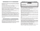
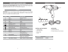
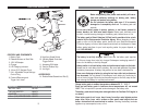
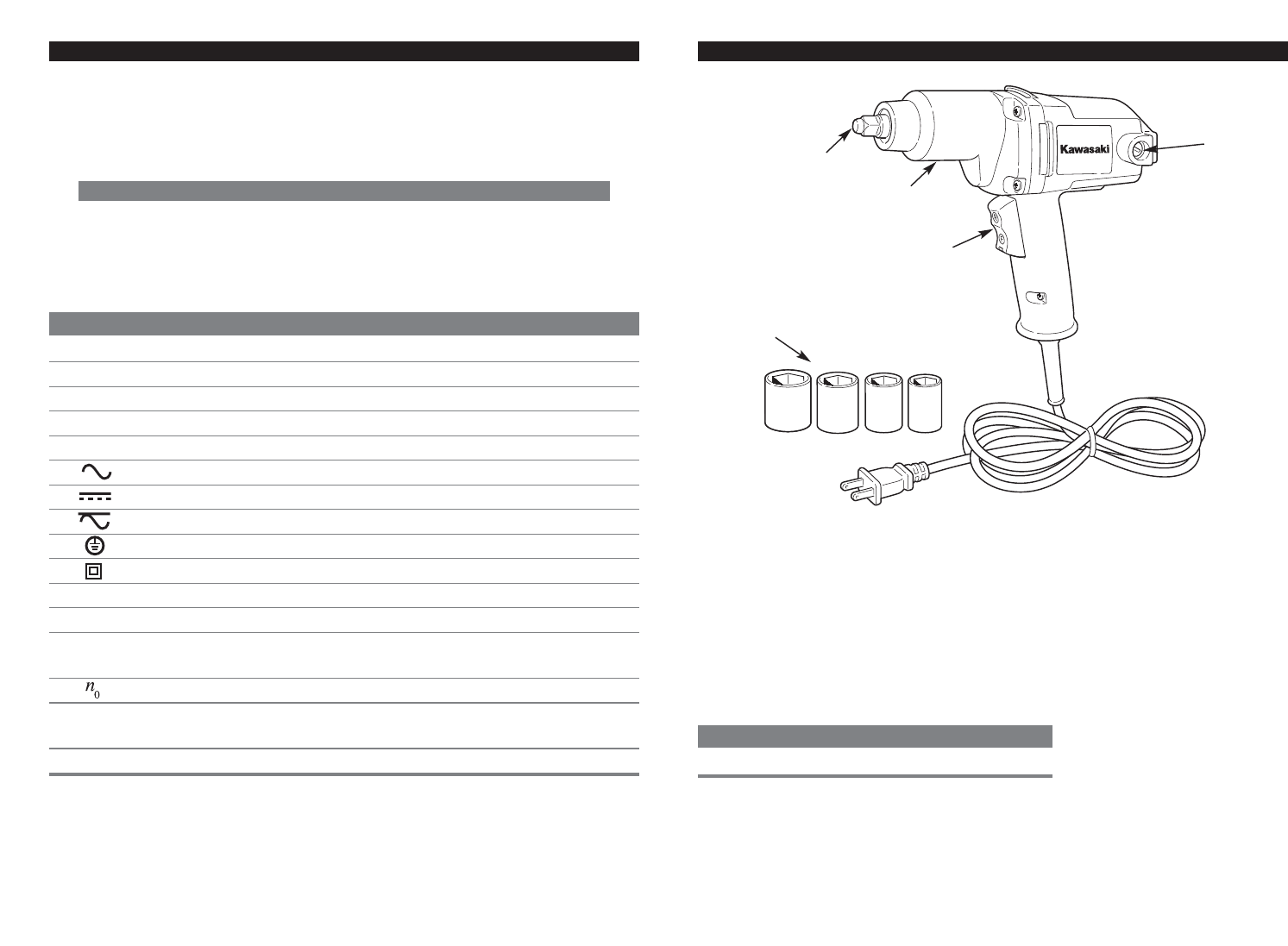
CONTROLS AND COMPONENTS:
1. Rocker Switch
2. Gear Enclosure
3. Brush Caps
4. Anvil
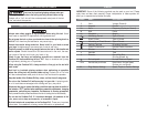
COMPONENT MODEL NUMBER
CARBON BRUSHES 690296
8
SPECIFIC SAFETY RULES AND/OR SYMBOLS
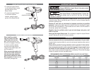
Hold tool by insulated gripping surfaces when performing an operation where the
cutting tool may contact hidden wiring. Contact with a “live” wire will also make
exposed metal parts of the tool “live” and shock the operator.
SYMBOLS
IMPORTANT: Some of the following symbols may be used on your tool. Please
study them and learn their meaning. Proper interpretation of these symbols will
allow you to operate the tool better and safer.
SYMBOL NAME EXPLANATION
V Volts Voltage (Potential)
A Amperes Current
Hz Hertz Frequency (Cycles per Second)
W Watt Power
Kg Kilograms Weight
Alternating Current Type of Current
Direct Current Type of Current
Alternating or Direct Current Type of Current
Earthing Terminal Grounding Terminal
Class II Construction Denotes Double Insulation
min Minutes Time
s Seconds Time
Diameter Size of Drill Bits,
Grinding Wheels, etc.
No load speed No-load Rotational Speed
.../min Revolutions per Minute Revolutions, Surface Speed,
Strokes, etc. per Minute
1,2,3, … Ring Selector Settings Speed, Torque or Position Settings
7
1
2
4
5
3
ACCESSORIES:
5. Impact Sockets (4)
6. Carbon Brushes (2) (not shown)