


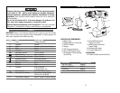

FUNCTIONAL DESCRIPTION
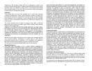
CONTROLS AND COMPONENTS:
1. Battery Pack
2. Release Buttons on Each Side
3. 120V AC Adapter
4. Charger
5. LED Charging Indicators
6. 10mm (3/8") Keyless Chuck
7. 25 Adjustable Torque Settings
Control Ring
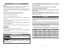
COMPONENT MODEL NUMBER
BATTERY PACK 690506
120V AC ADAPTER 690074
CHARGER 690072
10mm (3/8") KEYLESS CHUCK 690076
87
Disconnect the plug or remove the battery pack from tool and place the switch
in the locked or “OFF” position before making any assembly adjustments,
changing accessories, performing any inspection, maintenance or cleaning
procedures. Such preventive safety measures reduce the risk of starting the
tool accidentally.
Do not use the Cordless Drill if it has been damaged, left outdoors in the
rain, snow, wet or damp environments, or immersed in liquid.
Maintain labels and nameplates on the Cordless Drill. These carry important
information. If unreadable or missing, contact Alltrade for a replacement.
SYMBOLS
IMPORTANT: Some of the following symbols may be used on your tool. Please
study them and learn their meaning. Proper interpretation of these symbols will
allow you to operate the tool better and safer.
SYMBOL NAME EXPLANATION
V Volts Voltage (Potential)
A Amperes Current
Hz Hertz Frequency (Cycles per Second)
W Watt Power
Kg Kilograms Weight
Alternating Current Type of Current
Direct Current Type of Current
Alternating or Direct Current Type of Current
Earthing Terminal Grounding Terminal
Class II Construction Denotes Double Insulation
min Minutes Time
s Seconds Time
Diameter Size of Drill Bits,
Grinding Wheels, etc.
No load speed No-load Rotational Speed
.../min Revolutions per Minute Revolutions, Surface Speed,
Strokes, etc. per Minute
1,2,3, … Ring Selector Settings Speed, Torque or Position Settings
11
10
6
7
9
8
2
1
12
3
4
5
8. Forward/Reversing and
Trigger Lock Lever
9. Variable Speed Controlled
Trigger Switch
10. Accessory/Bit Holder
11. Comfort Rubber Grip
ACCESSORIES:
12. Double Ended Screwdriver Bits (2)