


EEDDGGEE GGRRIINNDDIINNGG
DDoo nnoott uussee eeddggee ggrriinnddiinngg wwhheeeellss ffoorr ccuutt--ooffff wwoorrkk,, ddeeeepp
ggrriinnddiinngg oorr ssuubbjjeecctt tthheemm ttoo aannyy ssiiddee pprreessssuurree
aass tthhiiss mmaayy lleeaadd ttoo bbrreeaakkaaggee
aanndd ppoossssiibbllee ppeerrssoonnaall iinnjjuurryy..
These wheels should be used for shallow cutting
and notching (less than 1/2" in depth). Keep the open side of the guard away
from the operator at all times.
Edge grinding should only be done with wheels specifically designed for this purpose.
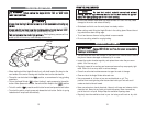
RREEMMOOVVIINNGG GGUUAARRDD FFOORR SSAANNDDIINNGG OORR UUSSIINNGG FFLLAATT WWIIRREE BBRRUUSSHHEESS
• Set the Angle Grinder on a flat surface with the spindle facing up.
• Remove the inner and outer flanges, unscrew spring washer and remove
the guard.
• Store these parts carefully.
• Replace the guard after the job is finished.
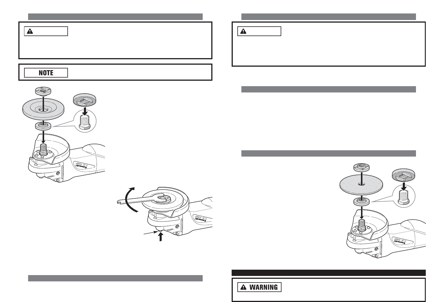
AATTTTAACCHHIINNGG SSAANNDDIINNGG DDIISSCC
• To remove the guard, see instructions
given in the “Removing Guard for
Sanding or Using Flat Wire Brushes”
Section above.
• Set the inner flange and outer flange on
the spindle.
• Push in the spindle lock button. Turn the
spindle until it locks into place.
• Once the spindle is locked, tighten the
sanding disc by hand.
OOPPEERRAATTIINNGG TTHHEE AANNGGLLEE GGRRIINNDDEERR
AAllwwaayyss uunnpplluugg tthhee ttooooll bbeeffoorree aatttteemmppttiinngg ttoo cchhaannggee tthhee
gguuaarrdd oorr aacccceessssoorriieess..
WARNING
12
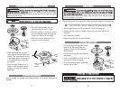
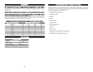
AATTTTAACCHHIINNGG WWHHEEEELLSS WWIITTHH DDEEPPRREESSSSEEDD CCEENNTTEERRSS
AAllwwaayyss cchheecckk tthhee ttooooll wwaarrnniinngg llaabbeell ffoorr tthhee rreeccoommmmeenndd--
eedd ssppeeeedd rraattiinngg oonn aacccceessssoorriieess..
Never run a wheel or brush over the rated
speed. Accessories exceeding the recommended speed may fly apart and cause
serious personal injury.
HHuubbbbeedd wwhheeeel
lss ddoo nnoott rreeqquuiirree mmoouunnttiinngg ffllaannggeess..
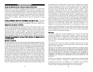
• Press the spindle lock firm and
insure there is no movement in the
spindle. Then while the spindle lock
is depressed tighten the locking nut
in a clockwise direction using the
pin spanner.
• Allow the Angle Grinder to run in
idle for at least a minute with the
grinding or cutting disc correctly
assembled.
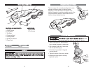
AATTTTAACCHHIINNGG WWIIRREE BBRRUUSSHHEESS
Wire cup brushes, not included, can be screwed directly on the spindle. No flanges are
necessary.
WARNING
11
SPINDLE
LOCK
BUTTON
• Place the backing washer over the
spindle making sure the fit is tight.
• Place the grinding or cutting disc on the
top of the backing washer ensuring the
bore fits into the step of the flange.
• Mount the concave recess side of the
locking nut over the spindle.