


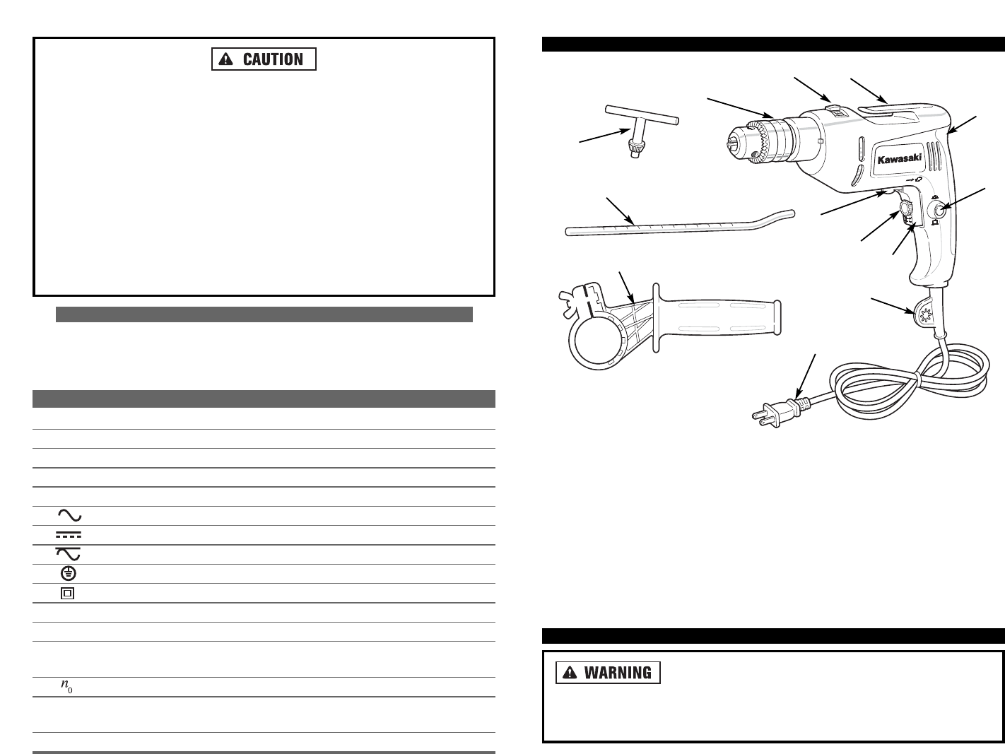
FFUUNNCCTTIIOONNAALL DDEESSCCRRIIPPTTIIOONN
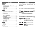
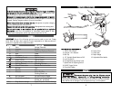
CCOONNTTRROOLLSS AANNDD CCOOMMPPOONNEENNTTSS::
1. 13mm (1/2”) Chuck
2. Hammer / Drill Selector
3. Belt Clip
4. 1/2” Variable Speed Hammer-Drill
5. Lock-On Switch
6. Forward/Reversing Switch Lever
7. Speed Control Adjusting Switch
8. On/Off Trigger Switch
9. Chuck Key Holder
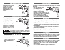
AASSSSEEMMBBLLYY
DDiissccoonnnneecctt tthhee ppoowweerr pplluugg ffrroomm tthhee AACC ppoowweerr ssoouurrccee
bbeeffoorree aannyy aasssseemmbbllyy,, aaddjjuussttmmeennttss,, oorr aaddd
diinngg//rreemmoovviinngg aacccceessssoorriieess..
Following this preventative step reduces the risk of the drill coming on acciden-
tally and the risk of damage to the workpiece and injury to the operator.
8
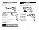
IIff tthhee bbiitt bbeeccoommeess bboouunndd iinn tthhee wwoorrkk ppiieeccee,, rreelleeaassee tthhee ttrriiggggeerr iimmmmeeddiiaatteellyy
aanndd pprreeppaarree ffoorr tthhee ttooool
l ttoo kkiicckkbbaacckk ttoowwaarrdd yyoouu..
Reverse the direction of rota-
tion, then back out the bit by slowly squeezing the trigger.
MMaakkee ssuurree aallll aacccceessssoorriieess aarree rraatteedd ffoorr tthhee rreeccoommmmeennddeedd ssppeeeedd ooff tthhee ddrriil
lll..
Brushes, grinding wheels and other accessories may fall apart if run at too high
a speed, sending dangerous debris flying at the operator.
NNeevveerr wweeaarr gglloovveess wwhheenn ooppeerraattiinngg tthhee ddrriillll..
Use gloves only when changing
hot bits and accessories to avoid burns.
HHaammmmeerr bbiittss aanndd ttoooollss ggeett hhoott dduurriinngg ooppeerraattiioonn..
Wear gloves when touching them.
D
Doo nnoott uussee iinn ddaammpp oorr wweett llooccaattiioonnss.. DDoo nnoott ooppeerraattee ttooooll iinn aann eexxpplloossiivvee
aattmmoosspphheerree
, such as in the presence of flammable liquids, gases or dust.
Power tools create sparks, which may cause an explosion or fire.
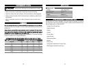
SSYYMMBBOOLLSS
IIMMPPOORRTTAANNTT::
Some of the following symbols may be used on your tool. Please
study them and learn their meaning. Proper interpretation of these symbols will
allow you to operate the tool better and safer.
SSYYMMBBOOLL NNAAMMEE EEXXPPLLAANNAATTIIOONN
V Volts Voltage (Potential)
A Amperes Current
Hz Hertz Frequency (Cycles per Second)
W Watt Power
Kg Kilograms Weight
Alternating Current Type of Current
Direct Current Type of Current
Alternating or Direct Current Type of Current
Earthing Terminal Grounding Terminal
Class II Construction Denotes Double Insulation
min Minutes Time
s Seconds Time
Diameter Size of Drill Bits,
Grinding Wheels, etc.
No load speed No-load Rotational Speed
.../min Revolutions per Minute Revolutions, Surface Speed,
Strokes, etc. per Minute
1,2,3, … Ring Selector Settings Speed, Torque or Position Settings
11
6
1
12
2
3
13
7
8
9
10. Power Cord
11. Chuck Key
12. Depth Gauge
13. Adjustable Side Handle
7
5
4
10