


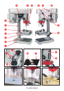
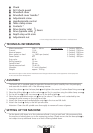


¾ Chuck
µ Drill chuck guard
¸ Drive/belt cover
¹ Drive/belt cover handle *
Ƹ Adjustment screw
ƹ Handle/spindle control
ƺ Table clamp screw
ƻ Contacts *
Ƽ Drive (motor side)
ƽ Drive (spindle side)
ƾ Depth stop with scale
ƿ Adjustment nut
* = form and type may differ from that shown in the illustrations
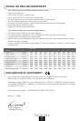
TECHNICAL INFORMATION
Mains connection: 230 V ~ 50 Hz Spindle speed: 1. Setting: 2600 rpm
Current: 1.9 A 2. Setting: 1750 rpm
Nominal power: 350 W 3. Setting: 1250 rpm
Nom. speed, no load: 1400 rpm (motor) 4. Setting: 0900 rpm
Power factor: 0.8 5. Setting: 0600 rpm
Duty cycle: 60 %
Drilling capacity: 13 mm
Spindle travel: 50 mm
Sound pressure level: 75 dB (A)
Vibration: 2.5 m/s
2
(vibration)
Weight: approx. 19.5 kg
We reserve the right to make technical modifications and changes without notice to the appearance of the equipment
in the course of further development.
ASSEMBLY
The bench drill is supplied ready to assemble. Remove the parts carefully from the packaging
and assemble the bench drill in the following manner:
1. Insert the column
² into the base plate ³ and tighten the screws (3 column/base fixing screws ·).
2. Place the drilling table » on to the column ² and fix it in position using the table clamp screw ƺ.
3. Fix the drill vice ´ (4 drill vice screws ¿) on to the drilling table ».
4. Place the pre-assembled motor unit
¶ on to the column. The motor unit is attached by two
hexagonal socket screws on the right hand side.
5. Attach the three armed handle/spindle control ƹ in the rise and fall shaft.
6. Attach the chuck ¾ firmly to the drill spindle cone.
Attention: Clean the drill spindle cone thoroughly to remove all traces of grease.
SETTING UP THE MACHINE
Set the bench drill down on a firm surface and level it using a spirit level. We recommend that
the machine is bolted down on to the supporting surface. Please ensure that the base plate ³ is
not subject to any additional forces as a result of being bolted down.
n
0
}
Gears
5