


B-3
OPERATION
B-3
------------------------------------------------------------------------
MOVING PARTS can injure.
• Keep guards in place.
• Keep away from moving parts.
• Only qualified personnel should
install, use or service this equipment.
------------------------------------------------------------------------
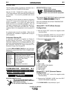
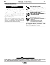
The engine MUST
BE COLD before seasonal
change over of the carburetor deicing kit.
When the AVERAGE AIR INTAKE TEMPERATURE
(Average Ambient) is:
Below 60°F / 15.5°C (Winter Season
Configuration)
1. With the engine OFF, remove the negative cable
from the battery.
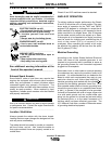
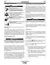
2. Push the FLEXIBLE HOSE fully onto the HEAT
COLLECTOR SHIELD outlet tube, see Figure 1.
3. Reconnect negative battery cable.
A. FUEL TANK
B. HEAT COLLECTOR SHIELD
C. FLEXIBLE HOSE
D. GEAR CLAMP
E. AIR FILTER
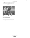
Above 60°F / 15.5°C (Summer Season
Configuration)
1. With the engine OFF, remove the negative cable
from the battery.
2. Remove the FLEXIBLE HOSE from the HEAT
COLLECTOR SHIELD outlet tube.
3. The FLEXIBLE HOSE is to be positioned per figure 2.
CLASSIC III AND IIID
Auxiliary Power
The AC auxiliary power, supplied as a standard, has a
rating of 3.0 kVA of 115/230 VAC (60 hertz).
With the 3.0 kVA, 115/230 VAC auxiliary power, one
115V duplex and one 230V grounding type receptacle
are provided. The circuit is protected with circuit
breakers.
The rating of 3.0 kVA permits a maximum continuous
current of 13 amps to be drawn from the 230 volt
duplex receptacle. Or a total of 26 amps can be
drawn from the 115 volt duplex receptacle. The 115
volt duplex receptacle has a configuration which per-
mits 15 amps to be drawn from either half. The total
combined load of all receptacles is not to exceed 3.0
kVA.
An optional power plug kit is available. When this kit
is specified, the customer is supplied with a plug for
each receptacle.
Carburetor Deicing Kit
A carburetor deicing kit is installed on Classic lll
welders leaving the factory. The purpose of the
Carburetor Deicing Kit is to prevent carburetor icing
when the outside temperature is 60°F/15.5°c or lower.
See Carburetor Deicing Kit Usage Instructions For
Seasonal Change Over on page B4.
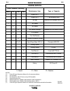
To obtain REPLACEMENT PARTS for the Carburetor
Deicing Kit contact WIS-CON TOTAL POWER COR-
PORATION.
Wis-Con Part# Description
10221023 Complete Carburetor Deicing Kit
10220028 Angled Heat Collector Shield
10060025 2”x18” Flexible Hose (Gates 28095)
X02355 #36 1.56”-2.50” Gear Clamp
XM32067 M10X70 Bolt
XM37004 3/8” Flat Washer
10250021 Notice Decal
LIT10278 Installation Instructions
CARBURETOR DEICING KIT
USAGE INSTRUCTIONS FOR SEA-
SONAL CHANGE OVER
ELECTRIC SHOCK can kill.
• Do not operate with panels open.
• Disconnect NEGATIVE(-) BATTERY
LEAD before servicing.
• Do not touch electrically live parts.
WARNING
FIGURE 1
E
D
C
B
A