


#()!!)$#
'#'P
?>>53D9?>?6!#(@??<E> 1>4
?2B1=1D93D?'#'P
O(8EDD85G5<45B?66
• Connect per instructions on the appropriate connec-
tion diagram in Section F.
?>>53D9?> ?6 %'#-!(%$$!*#D?D85
'1>75BP
Connection of the Prince XL Spool Gun requires the
use of the K1849-1 Adapter Module.
O(8EDD85,5<45B?66
• For electrode Positive, connect the electrode cable
to the "+" terminal of the welder and work cable to
the "-" terminal of the welder. For electrode
Negative, connect the electrode cable "-" terminal of
the welder and work cable to the "+" terminal of the
welder.
• Connect the Control Cable of the Spool Gun to the
Adapter Module and connect the Control Cable of
the Adapter Module to the Welder.
• Connect the Gas Hose.
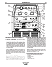
• Set the MODE switch to the "CV-WIRE " position.
• Set the "WELD TERMINALS" switch to "WELD
TERMINALS ON".
• Set the "ARC CONTROL" knob to "0" initially and
adjust to suit.
• Set the “IDLE” switch to the “HIGH” position.
?>>53D9?>?6D85!#D?D85'#'P
(8ED?66G5<45B256?B5=1;9>71>I5<53DB931<3?>
>53D9?>C
--------------------------------------------------------------------------------
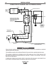
The LN-25 with or without an internal contactor may
be used with the RANGER® 305D. See the appropri-
ate connection diagram in Section F.
(8EDD85G5<45B?66
2. For electrode Positive, connect the electrode
cable from the LN-25 to the "+" terminal of the
welder and work cable to the "-" terminal of the
welder. For electrode Negative, connect the elec-
trode cable from the LN-25 to the "-" terminal of
the welder and work cable to the "+" terminal of
the welder.
3. Attach the single lead from the front of the LN-25
to work using the spring clip at the end of the lead.
This is a control lead to supply current to the wire
feeder motor; it does not carry welding current.
4. Set the MODE switch to the "CV-WIRE " position.
5. Set the "WELD TERMINALS" switch to "WELD
TERMINALS ON"
6. Set the "ARC CONTROL" knob to "0" initially and
adjust to suit.
7. Set the "IDLE" switch to the "AUTO" position.
When not welding, the RANGER® 305D engine
will be at the low idle speed. If you are using an
LN-25 with an internal contactor, the electrode is
not energized until the gun trigger is closed.
8. When the gun trigger is closed, the current sens-
ing circuit will cause the RANGER® 305D engine
to go to the high idle speed, the wire will begin to
feed and the welding process started. When weld-
ing is stopped, the engine will revert to low idle
speed after approximately 12 seconds unless
welding is resumed.
6I?E1B5EC9>71>!#G9D8?ED1>9>D5B>1<3?>
D13D?BD855<53DB?45G9<<255>5B79J54G85>D85
'1>75BP9CCD1BD54
--------------------------------------------------------------------------------
,'##
*)$#