


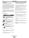
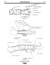

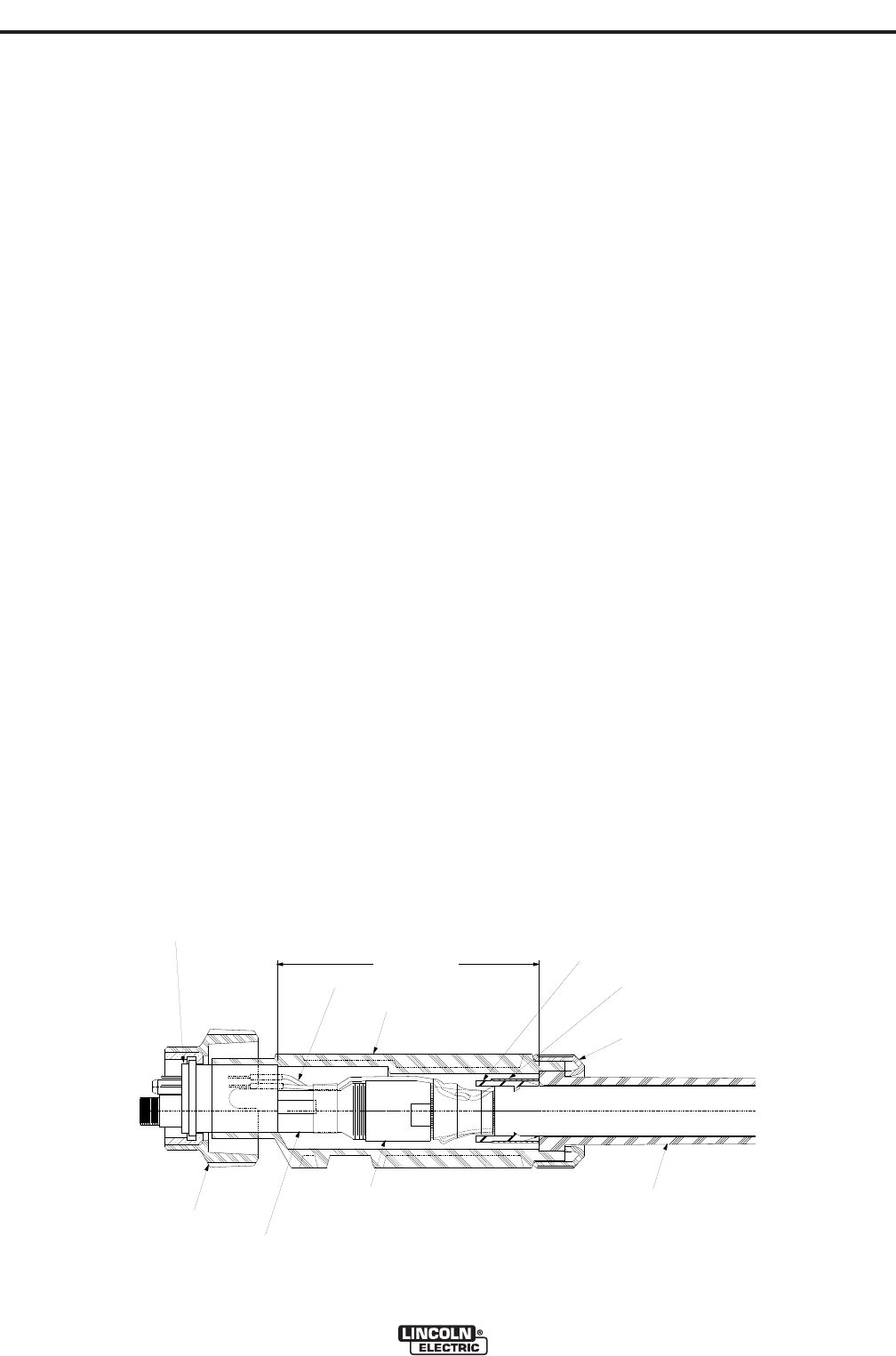
4.10 (104 mm)
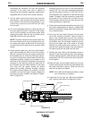
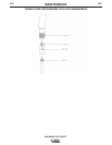
Terminal Lead Assembly
Cable Handle
Central Adapter Assembly
Collar Nut
Incoming Connector Assembly
Connector Nut
Cable Boot
Strain Relief
Strain Relief Housing
Boot Nut
-
FIGURE E.5
MAINTENANCE
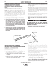
e) Remove the incoming connector from the cable by
unscrewing the connector nut from the incoming
connector. If the cable inner tube is difficult to
remove from the connector assembly, carefully slit it
lengthwise with a knife up to the brass connector.
f) Cut the cable control wires where they meet the
cable jacket or else unsolder the connection where
they connect to the terminal lead assembly. If you
cut the wires, strip the cut end 3/8 inch (9.5 mm)
from the end.
g) Cut off the damaged section of cable and strip off
the outer jacket as shown in Figure E.2. Be careful
not to cut the insulation on the control wires while
stripping the jacket. Strip the red and white control
leads 3/8 inch (9.5 mm) from the end.
NOTE: The cable contains three control leads. Any
two control leads can be used, provided the two col-
ors used are the same at both ends. The extra lead
is a spare that can be used if one of the other leads
breaks.
h) Check that the cable boot, boot nut, cable handle,
strain relief housing and collar nut are on the cable.
Slip the connector nut over the copper strands with
the threaded end out. Orient the connector assem-
bly so the red and white control leads will have the
straightest possible routings to the sockets on the
back side of the connector. Assemble the incoming
connector to the cable by forcing the steel tube of
the connector into the inside diameter of the cable
inner tube until the copper strands are butted
against the incoming connector shoulder. Keeping
the copper strands against the shoulder, pull the
connector nut over the copper strands, engage the
incoming connector threads, and tighten in place.
Refer to Figure E.3.
NOTE: For best results, insert a rod through the
connector and into the core of the cable approxi-
mately 5.00” (127 mm) when pushing the connector
tube into the cable core tube. A .219”/.240” (5.6-6.1
mm) diameter rod is required for 300 and 400 amp
cables. To tighten, hold the connector in place while
turning the nut, then remove the rod from the core.
This procedure assures the inner core does not kink
while assembling or tightening.
j) Solder the terminal lead assemblies from step (f) to
the control leads stripped in step (g). Insulate both
soldered connections using either heat shrink tub-
ing or electrical tape.
k) Fully insert the two control lead pins into the sock-
ets on the incoming connector. Tape the leads in
place in the necked down area of the connector.
Keeping the leads as close to the connector and nut
as possible, tape the insulated, soldered connec-
tions and the spare lead to the cable in the area
between the cable jacket and connector nut. This
must be done neatly and kept as low as possible or
the cable handle will not slide over this area.
l) Position the strain relief to the dimension shown in
Figure E.5 and secure with the strain relief housing.
On older cables install the cable clamp on the cable
jacket within 1/8” (3.2 mm) from the end of the jack-
et and tighten.
m) Slide the collar nut and cable handle over the con-
nection and into place. Anchor the cable handle with
the screw removed in step (c). Slide the boot and
boot nut into place and tighten.
NOTE: If the cable handle becomes difficult to slide
over connection, try rotating it.
n) Install and trim the liner per “Removal, Installation
and Trimming Instructions for Magnum® Liners”.
MAGNUM® FAST-MATE™
D-5D-5