


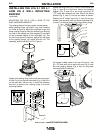
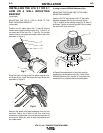


Rotate the hinge rod (Fig. 4, Item D) so the stop pin
(Fig. 4, Item B) is in the front. Mount the hanging
adapter (Fig. 5, Item D) to the hinge rod using (2)
1.75” bolts with washers and nuts. Mount the spring
bracket (Fig. 5, Item F) into the two holes as shown.
Position one 8” rubber band (Fig. 5, Item A) and the
flexible hose supplied with the mounting bracket (Fig.
5, Item E) on the red plastic ring of the rotating hinge.
Put another rubber band on the top of the arm. Use
(2) 1.75” bolts with nuts to mount the arm (Fig. 6, Item
B) to the hanging adapter (Fig. 6, Item A), using both
mounting holes as indicated.
AB
Fig. 6
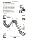
INSTALLING THE LFA 3.1 OR 4.1
ARM ON A WALL MOUNTING
BRACKET
(continued)
MOUNTING THE LFA 3.1 OR 4.1 ARM TO THE
WALL-MOUNTING BRACKET
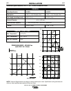
The rotating hinge of the arm comes in three pieces:
Metal rotating hinge, red plastic ring, and clamping
pin. Refer to Figure 3. Mount the red plastic ring to the
metal rotating hinge by fitting the clamping pin through
the hole in the rotating rod, and snapping it into place
on the U-shaped indents on the red plastic ring. The
lip of the ring should fit securely against the top edge
of the rotating flange, yet rotate with the rod. The
assembly should look like Part C in Figure 4.
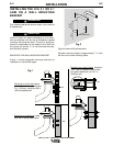
Position the rotating hinge on the wall mounting brack-
et (See Fig. 4) so that the cable hole (Fig. 4, Item A) is
on the wall side. Use the four 3” bolts with washers
and nuts to secure the rotating hinge to the wall
mounting bracket.
A
B
D
E
F
C
Fig. 5
A-4
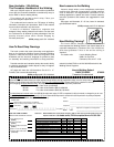
INSTALLATION
LFA 3.1 & 4.1 FUME EXTRACTION ARMS
A-4
D
E
C
B
A
Fig. 4
2
1
3
Fig. 3