


#()!!)$#
#%*) *( # (*%%!. ,'
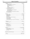
$#(')$#(
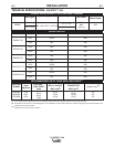
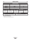
Refer to Specification in this Installation Section for
recommended fuse, wire sizes and type of the copper
wires. Fuse the input circuit with the recommended
super lag fuse or delay type breakers (also called
"inverse time" or "thermal/magnetic" circuit breakers).
Choose input and grounding wire size according to
local or national electrical codes. Using input wire
sizes, fuses or circuit breakers smaller than recom-
mended may result in "nuisance" shut-offs from
welder inrush currents, even if the machine is not
being used at high currents.
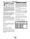
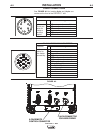
#%*)+$!)(!)$#
Welders are shipped connected for 460 Volt input
voltage. To move this connection to a different input
voltage, see the diagram located on the inside panel
in the reconnect/input connection area, also illustrat-
ed below. If the Auxiliary lead (indicated as ‘A’) is
placed in the wrong position and power is applied to
the machine, the machine will protect itself and dis-
play an error message:
• "Err" "058" will be shown on the display.
• The control board and switch boards will blink out
error 58 on their status leds.
• The weld output will be turned off and the control
board will force itself into an idle state.
• The machine will need to have the misconnect
condition removed before it will recover.
!)'($ can kill
$#!. &*!!)'#
($*! $##) ) #%*)
!( )$) !-)Q
$##)$#(($*!"#$'
#,)!!!$!##)$#!
!)'! $( #)$##)$#
'" !$) $#)#($ )
'$##)#%*)(($$' $)
"#!*')$ $($". '(*!)
#$!.#*'.$')
----------------------------------------------------------------------
,'##
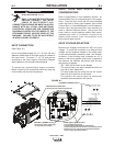
#%*)$##)$#
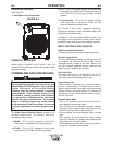
(See Figure A.1)
Use a three-phase supply line. A 1.40 inch (36 mm)
diameter access hole for the input supply is located on
the case back. Connect L1, L2, L3 and ground
according to the Input Supply Connection Diagram
decal located on the internal horizontal panel.
To access the reconnect/input supply connection
blocks, remove the 8 screws that secure the case top
of the welder and remove the case top.
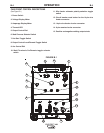
!-)Q
RECONNECT TERMINAL BLOCK
• Reconnects auxiliary transformers
for the proper input voltages
POWER SUPPLY TERMINAL BLOCK
• Line Cord/Cable attaches here.
• A ground terminal marked with the symbol shown
is provided separate from this block for connecting the ground
lead of the line cord. (See your local and national electrical
codes for proper grounding methods.)
POWER SUPPLY ACCESS HOLE
• Route input power cable through this hole.
RECONNECT TERMINAL BLOCK
RECONNECT TERMINAL BLOCK
• Reconnects auxiliary transformers
for the proper input voltages
POWER SUPPLY TERMINAL BLOCK
• Line Cord/Cable attaches here.
• A ground terminal marked with the symbol shown
is provided separate from this block for connecting the ground
lead of the line cord. (See your local and national electrical
codes for proper grounding methods.)
POWER SUPPLY ACCESS HOLE
• Route input power cable through this hole.
RECONNECT TERMINAL BLOCK
*'