


%&(*%$
".*R
>A6C286:DA=2J#6E6C
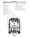
• Prior to STICK or TIG operation (current flow), the
meter displays preset current value.
• Prior to CV operation, the meter displays four dash-
es indicating non-presettable AMPS.
• During welding, this meter displays actual average
amps.
• After welding, the meter holds the actual current
value for 5 seconds. The displays blink indicating
that the machine is in the "hold" period.
•Output adjustment while in the "hold" period results
in the "prior to operation" characteristics
-6=5*6C>:?2=D%?(6>@E6*@88=6)H:E49
• This switch determines the trigger location.
• When set to the W%$X position, the weld terminals
are at OCV (open circuit voltage) and ready to weld.
• When set to the W(#%*X position, output is
enabled through a remote trigger.
@?EC@="@42=(6>@E6*@88=6)H:E49
• Set the switch to W"@42=X to control output at the
machine by the Output Control dial.
• Set the switch to W(#%*X to control output via a
remote device (K857 hand amptrol or K870 foot
amptrol) connected to the A:? remote connector
or a wire feeder connected to the A:? connector.
*96C>2=":89E
• This status light indicates when the power source
has been driven into thermal overload. If the output
terminals were %$, the output will be turned back
on once the unit cools down to an acceptable tem-
perature level. If the unit was operating in the
(#%* mode, the trigger will need to be
opened before or after the thermal has cleared and
closed after the machine has cooled down to an
acceptable temperature to establish output.
,(R ,%"*(+*%$,
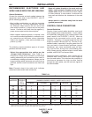
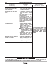
$*%("*
There are 2 indicator lights on the case front of the
Flextec™ 450 CE above the Voltage LCD Display to
indicate the status of VRD operation.
• A green light indicates the OCV (open circuit volt-
age) is less than 35V.
• A red light indicates the OCV is at or above 35V.
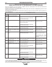
VRD™ is enabled via a dip switch on the Control
P.C. board (see Figure B.3). This switch must be in
the “On” position for the VRD™ function to be active
and the lights to be enabled. If VRD™ is enabled,
both lights will illuminate for 5 seconds at power up.
For each weld mode, the VRD™ lights function as
shown in Table B.1:
,(?5:42E@C":89ED
*"
+(
It is normal for the lights to alternate between colors while welding.
Mode
VRD “ON”
Green (OCV reduced)
Green or Red (depends on weld voltage)*
Red (OCV Not Reduced)
Weld Terminals ‘ON’
Red (OCV Not Reduced)
Weld Terminals Remotely Controlled
Gun Trigger Closed
Green (NO OCV)
Weld Terminals Remotely Controlled
Gun Trigger Open
Green or Red (depends on weld voltage)*
CC-MMAW
CC-GTAW
CV-GAS
C V-Innershield
OCV
While welding
OCV
While welding
VRD “OFF”
No lights are
active
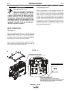
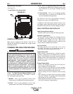
Dip Switch Location on Control P.C. Board
Location of Control P.C. Board
ON
1 2 3 4 5 6 7 8
OFF
VRD Mode Setting
- Switch #5 in the “ON” Position
Dip Switch Location on Control P.C. Board
Location of Control P.C. Board
ON
1 2 3 4 5 6 7 8
OFF
VRD Mode Setting
- Switch #5 in the “ON” Position