


B-4
OPERATION
POWER WAVE 455 STT
B-4
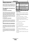
WELDING CAPABILITY
The POWER WAVE 455 STT is rated at 60 Hz.
450A@ 38V. 100% duty cycle or 570A@ 43V 60%
duty cycle - 50 Hz. 400A@ 36V, 100% duty cycle or
500A@40V 60% duty cycle. The machine is capable
of higher outputs at lower duty cycles. For the STT
process only, the machine is rated at 325 amps, 100%
duty cycle.
If the duty cycle is exceeded, a thermostat will shut off
the output until the machine cools to a reasonable
operating temperature.
LIMITATIONS
• The Power Wave is not recommended for process-
es other than those listed.
• The Power Wave can only be used with Power
Feed wire feeders. Other models of Lincoln feed-
ers, or any models of non-Lincoln wire feeders, can-
not be used.
COMPATIBLE LINCOLN EQUIPMENT
All Lincoln Power Feed™ Wire Feeders.
POWER SOURCE OPERATION
DUTY CYCLE AND TIME PERIOD
The POWER WAVE 455 STT is rated at 60 Hz.
450A@ 38V. 100% duty cycle or 570A@ 43V 60%
duty cycle - 50 Hz. 400A@ 36V, 100% duty cycle or
500A@40V 60% duty cycle. The duty cycle is based
upon a ten minute period. For the STT process only,
the machine is rated at 325 amps, 100% duty cycle. A
60% duty cycle represents 6 minutes of welding and 4
minutes of idling in a ten minute period.
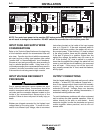
CASE FRONT CONTROLS
All operator controls and adjustments are located on
the case front of the Power Wave.
1. POWER SWITCH: Controls input power to the
Power Wave.
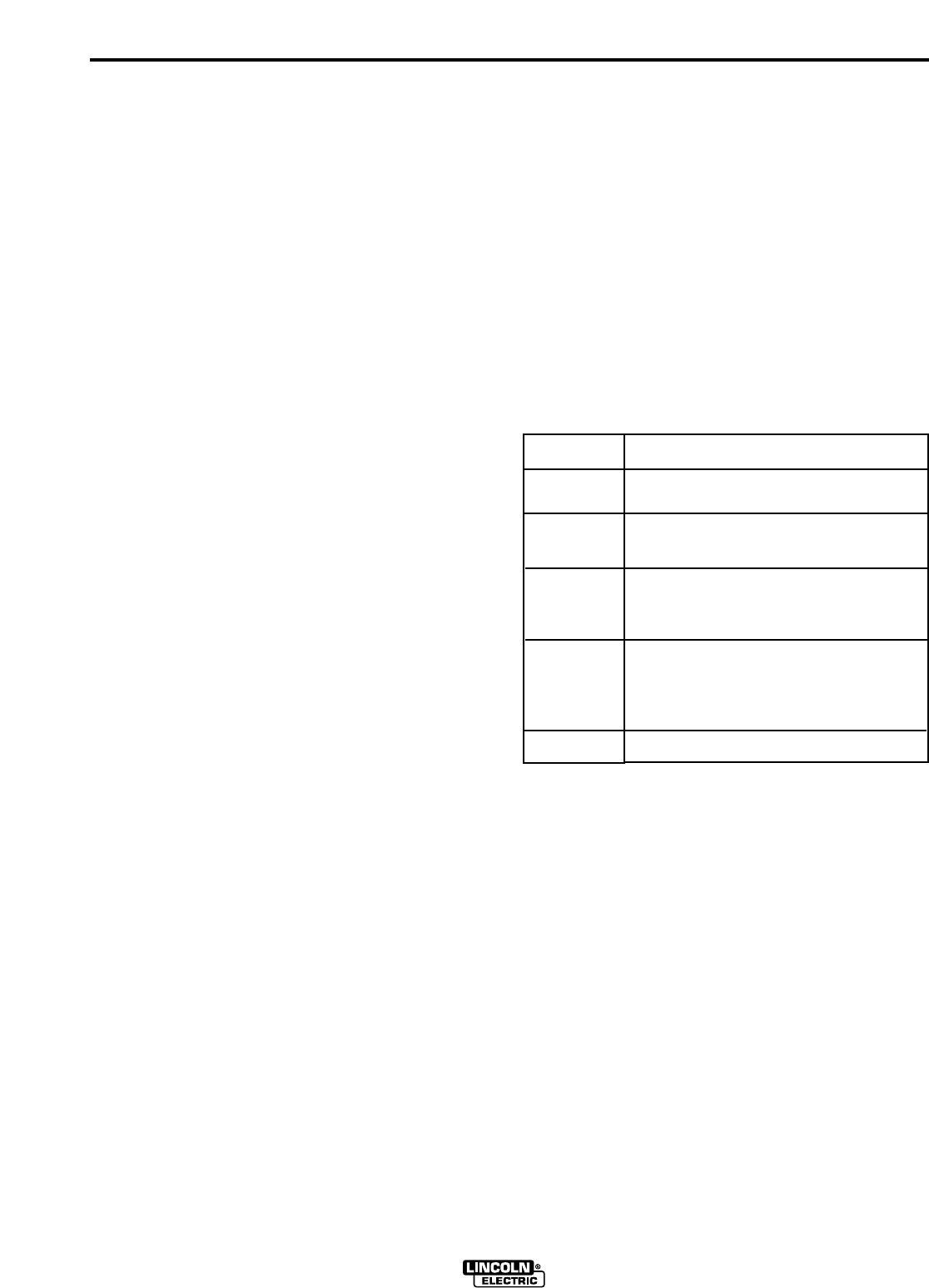
2. STATUS LIGHT: A two color light that indicates
system errors. Normal operation is a steady green
light. Error conditions are indicated as follows:
NOTE: The POWER WAVE 455 STT status light will
flash green, and sometimes red and green, for up to
one minute when the POWER WAVE 455 STT is first
turned on. This is a normal situation as the machine
goes through a self test at power up.
3. HIGH TEMPERATURE LIGHT (thermal overload):
A yellow light that comes on when an over temper-
ature situation occurs. Output is disabled until the
machine cools down. When cool, the light goes
out and output is enabled.
4. 10 AMP WIRE FEEDER CIRCUIT BREAKER:
Protects 40 volt DC wire feeder power supply.
5. 10 AMP AUXILIARY POWER CIRCUIT BREAK-
ER: Protects 110 volt AC case front receptacle
auxiliary supply.
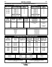
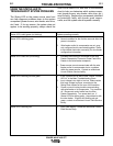
Light
Condition
Steady Green
Blinking
Green
Alternating
Green and
Red
Steady Red
Blinking Red
Meaning
System OK. Power source communicating nor-
mally with wire feeder and its components.
Nothing connected to Wire Feeder
Receptacle.
Recoverable system fault.See
Troubleshooting Section.
Non-recoverable system fault. Must turn
power source off, find source of error, and
turn power back on to reset. See
Troubleshooting Section.
See Troubleshooting Section.