


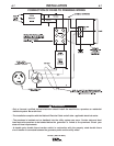
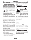

STANDBY POWER CONNECTIONS
The DX450 is suitable for temporary, standby or
emergency power using the engine manufacturer’s
recommended maintenance schedule.
The DX450 can be permanently installed as a standby
power unit for 240 VAC, 3 wire, single phase, 50 amp
service. Connections must be made by a licensed
electrician who can determine how the 120/240 VAC
power can be adapted to the particular installation and
comply with all applicable electrical codes.
• Install the double-pole, double-throw switch
between the power company meter and the premis-
es disconnect. Switch rating must be the same or
greater than the customer’s premises disconnect
and service over current protection.
• Take necessary steps to assure load is limited to
the capacity of the generator by installing a 50 amp,
240 VAC double pole circuit breaker. Maximum
rated load for each leg of the 240 VAC auxiliary is
50 amperes. Loading above the rated output will
reduce output voltage below the allowable - 10% of
rated voltage which may damage appliances or
other motor-driven equipment and may result in
overheating of the engine and/or alternator wind-
ings.
• Install a 50 amp, 120/240 VAC plug to the double-
pole circuit breaker using No. 6, 4 conductor cable
of the desired length.
• Plug this cable into the 50 Amp, 120/240 Volt recep-
tacle on the case front.
• Only a licensed, certified, trained electrician
should install the machine to a premises or resi-
dential electrical system. Be certain that:
• The installation complies with the National
Electrical Code and all other applicable electri-
cal codes.
• The premises is isolated and no feedback into
the utility system can occur. Certain laws require
the premises to be isolated before the generator
is linked to the premises. Check your local
requirements.
------------------------------------------------------------------------
A-6
INSTALLATION
DX450 (RED-D-ARC)
A-6
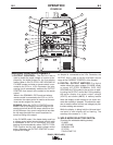
AUXILIARY POWER RECEPTACLES
Start the engine and set the “IDLER” control switch to the
“High Idle” mode. Voltage is now correct at the receptacles
for auxiliary power. This must be done before a tripped
GFCI module can be reset properly. See the MAINTE-
NANCE section for more detailed information on testing
and resetting the GFCI module.
The auxiliary power of the DX450 consists of two 20 Amp-
120 VAC (5-20R) duplex receptacles with GFCI protection,
one 50 Amp 120/240 VAC (SS2-50R) receptacle and one
50 Amp 240VAC Three-Phase (15-50R) receptacle.
The auxiliary power capacity is 12,000 watts Peak, 11,000
Watts Continuous of 60 Hz, single phase power. The auxil-
iary power capacity rating in watts is equivalent to volt-
amperes at unity power factor. The max permissible current
of the 240 VAC output is 50amps.
The 240 VAC output can be split to provide two separate
120 VAC outputs with a max permissible current of 50
Amps per output to two separate 120 VAC branch circuits
(these circuits cannot be paralleled). Output voltage is with-
in ± 10% at all loads up to rated capacity.
The Three-Phases auxiliary power capacity is 19,000 watts
peak, 17,000 watts continuous. The maximum current is 45
amps.
120 V DUPLEX RECEPTACLES AND GFCI MODULES
A GFCI Module protects the two 120V auxiliary power
receptacles.
A GFCI (Ground Fault Circuit Interrupter) is a device to pro-
tect against electric shock should a piece of defective
equipment connected to it develop a ground fault. If this sit-
uation should occur, the GFCI module will trip, removing
voltage from the output of the receptacle. If a GFCI module
is tripped see the MAINTENANCE section for detailed
information on testing and resetting it. A GFCI module
should be properly tested at least once every month.
The 120 V auxiliary power receptacles should only be used
with three wire grounded type plugs or approved double
insulated tools with two wire plugs. The current rating of
any plug used with the system must be at least equal to the
current capacity of the associated receptacle.
NOTE: The 240 V receptacle has two 120 V circuits, but
are of opposite polarities and cannot be paralleled.
All auxiliary power is protected by circuit breakers. The
120V has 20 Amp circuit breakers for each duplex recepta-
cle. The 120/240V Single Phase and the 240V Three-
Phases have a 50 Amp 3-pole Circuit Breaker that discon-
nects both hot leads and all Three Phases simultaneously.
WARNING