


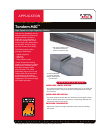

Tandem MIG
The future of welding is here.
®
APPLICATION
10/16
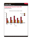
High-Speed and High-Deposition Welding
WAVEFORM CONTROL TECHNOLOGY
TM
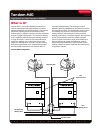
Using Tandem MIG
Understanding Operating Variables
The general rules governing operating variables for single wire GMAW arc welding also apply to Tandem MIG
welding. However there are additional considerations that must be kept in mind when welding with multiple arcs.
Since the two arcs will interact, the type of power fed to each arc, the wire feed speed ratio between lead and trail,
the arc lengths, the wire positioning, and torch angles must be set correctly. The enclosed procedures are starting
points and may need to be altered based on specific application conditions. Adherence to the following guidelines
will assist in achieving the maximum potential of the process.
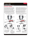
Lead Arc
The lead arc creates the majority of the penetration and should represent the majority of the total deposition
rate of the process. When using like diameter electrodes for the lead and the trail, the lead should represent
approximately 60% of the total wire feed. In the case where a larger wire diameter is used as a lead (for added
penetration) the lead should represent approximately 60% or more of the total deposition. The lead arc can be
operated in a Tandem pulse, CV or Power mode. Pulse is recommended for the high deposition procedures.
Power mode or CV may be used for greater lead arc stability in high travel speed applications.
Trail Arc
The trail arc is used to cool the weld pool and control the bead contour and is always operated in the Tandem
pulse mode. The trail should be kept directly in line with the lead arc and focused on the center of the weld pool.
The trail wire should represent approximately 40 % of the process deposition rate. The Tandem MIG trail pulse
waveforms are designed to operate at low voltages to limit arc interaction and minimize arc blow.
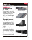
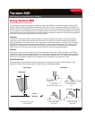
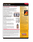
Torch Positioning
Torch positioning may be altered for specific applications. A 5-degree push angle is recommended for high
deposition welding. A (0-5)-degree angle is recommended for high speed welding.
Push Angle
Travel
Directionl
A 5-degree push angle
is recommended
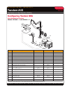
Flat Welds
(Beveled Butt, Fillets, Laps
Horizontal Welds
Lap
Horizontal Welds
Small Fillet
Horizontal Welds
Large Fillet
Travel Angle
Joint Angle
90°
65°
45°
40°
Push Angle
Travel
Direction
1/2” Wire Dia.