


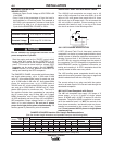
#()!!)$#
'#'P%(
+$!)*!+$!)'%)!
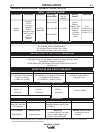
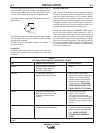
The 120/240 volt receptacle can supply up to 40
amps of 240 volt power to a two wire circuit, up to 40
amps of 120 volts power from each side of a three
wire circuit (up to 80 amps total). Do not connect the
120 volt circuits in parallel. Current sensing for the
automatic idle feature is only in one leg of the three
wire circuit as shown in the following column.
+*%!-'%)!(
A GFCI (Ground Fault Circuit Interrupter) electrical
receptacle is a device to protect against electric shock
should a piece of defective equipment connected to it
develop a ground fault. If this situation should occur,
the GFCI will trip, removing voltage from the output of
the receptacle. If a GFCI receptacle is tripped see the
MAINTENANCE section for detailed information on
testing and resetting it. A GFCI receptacle should be
properly tested at least once every month.
The 120V auxiliary power receptacles should only be
used with three wire grounded type plugs or approved
double insulated tools with two wire plugs.
The current rating of any plug used with the system
must be at least equal to the current load through the
associated receptacle.
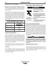
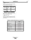
+?<D%81C5'535@D13<5G9D8B?E>4
The 480 volt receptacle can supply 12.6 amps of 3
phase power, or up to 15 amps of single phase
power. A NEMA plug L16-20P is required to use this
receptacle. The ground (GND) connection is connect-
ed to the machine frame, it is #$) the neutral of the
three phase connection, and should under no circum-
stances be connected to the neutral of any 3 phase
load. ?>?D3?>>53D+@81C5D?C9>7<5@81C5
@B5=9C5CG9B9>7
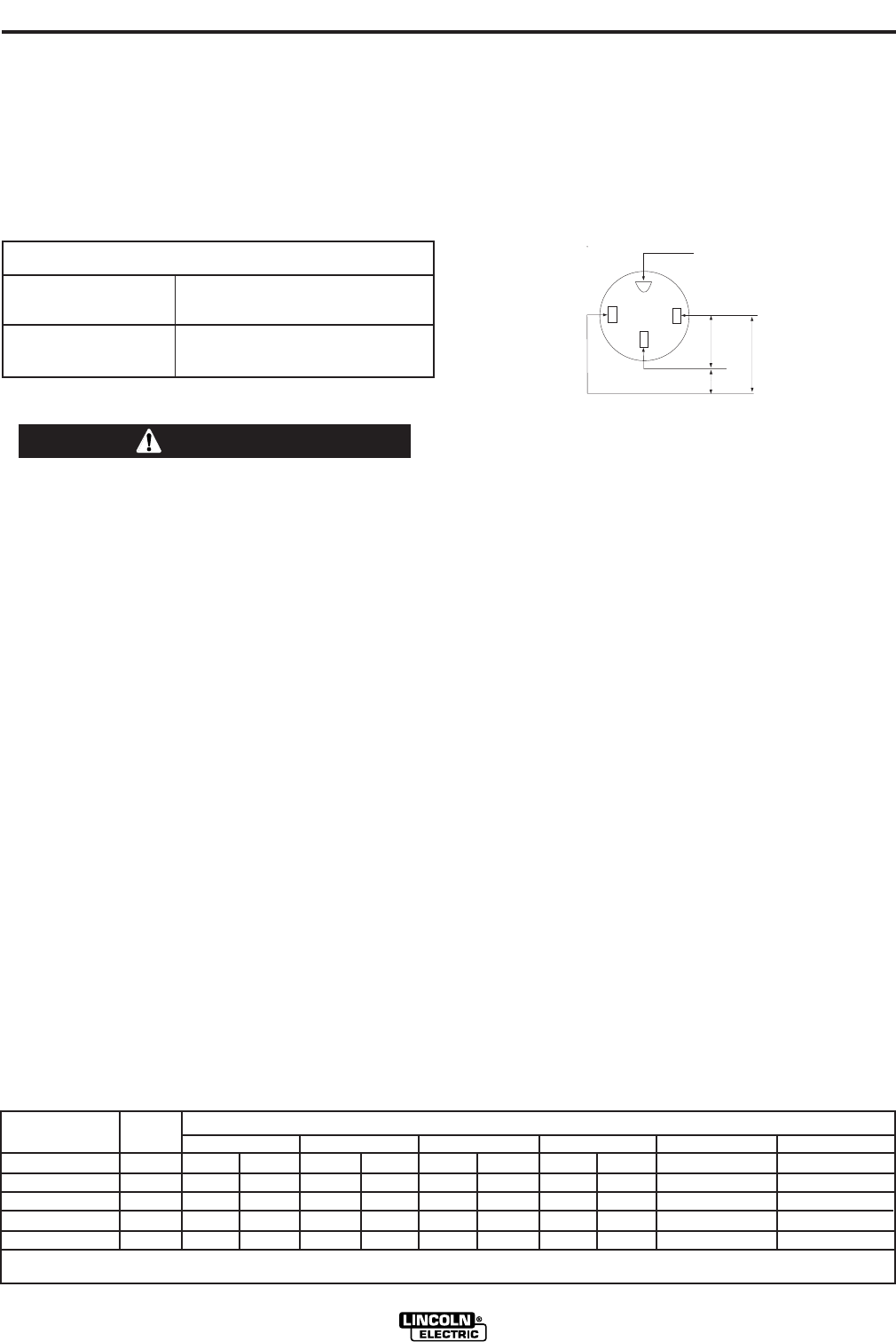
GND
120 V
120 V*
240 V
*Current Sensing for Automatic Idle.
(Receptacle viewed from front of Machine)
GND
120 V
120 V*
240 V
*Current Sensing for Automatic Idle.
(Receptacle viewed from front of Machine)
,!'$%')$#
,!'$*)%*)
• Maximum Open Circuit Voltage at 3700 RPM is 80
Volts RMS.
• Duty Cycle is the percentage of time the load is
being applied in a 10 minute period. For example, a
60% duty cycle represents 6 minutes of load and 4
minutes of no load in a 10 minute period. Duty
Cycle for the RANGER® 3 PHASE is 100%.
*-!'.%$,'
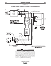
?>?D3?>>53D 1>I @<E7CD81D 3?>>53DD? D85
@?G5BB535@D13<5C9>@1B1<<5<
------------------------------------------------------------------------
Start the engine and set the “IDLER” control switch
to the “High Idle” mode. Set the “CONTROL” to 10.
Voltage is now correct at the receptacles for auxiliary
power. This must be done before a tripped GFCI
receptacle can be reset properly. See the "#)
## section for more detailed information on
testing and resetting the GFCI receptacle.
The RANGER 3 PHASE can provide both three phase
and single phase power, up to 11,500 watts of 480
volts AC, three phase 60Hz power for peak use, and
up to 10,500 watts of 480 volts AC, three phase 60Hz
power for continuous use, up to 10,500 watts of
120/240 volts AC, single phase 60Hz power for peak
use, and up to 9,500 watts of 120/240 volt AC, single
phase 60Hz power for continuous use. The front of
the machine includes four receptacles for connecting
the AC power plugs; one 20 amp 480 volt 3 phase
NEMA receptacle, one 50 amp 120/240 volt NEMA
14-50R receptacle and two 20 amp 120 volt NEMA 5-
20R receptacles. Output voltage is within +/-10% at all
loads up to rated capacity. ? >?DEC5@81C5
@?G5B1>4C9>7<5@81C5@?G5BC9=E<D1>5?EC<I All
auxiliary power is protected by cuircuit breakers.
*)$#
'#'P%(
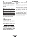
?>CD1>DEBB5>D 210 Amps DC @ 25 Volts
?>CD1>D+?<D175 200 Amps DC @ 20 Volts
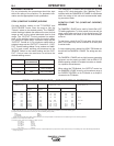
'#'%(HD5>C9?>?B4!5>7D8'53?==5>41D9?>C
(Use the shortest length extension cord possible sized per the following table.)
Maximum Allowable Cord Length in ft. (m) for Conductor Size
Conductor size is based on maximum 2.0% voltage drop.
14 AWG 12 AWG 10 AWG 8 AWG 6 AWG 4 AWG
Current
(Amps)
15
20
15
20
40
Voltage
Volts
120
120
240
240
240
Load
(Watts)
1800
2400
3600
4800
9500
30
60
(9)
(18)
40
30
75
60
(12)
(9)
(23)
(18)
75
50
150
100
50
(23)
(15)
(46)
(30)
(15)
125
88
225
175
90
(38)
(27)
(69)
(53)
(27)
175
138
350
275
150
300
225
600
450
225
(91)
(69)
(183)
(137)
(69)
(53)
(42)
(107)
(84)
(46)