


INSTALLATION
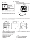
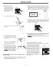
2. Attach the control cable
Amphenol, gas line con-
nector, and electrode
cable terminal to their
respective connectors
on the rear panel of the
Control Module.
3. At the other end of the cable:
Connect the gas line to the gas cylinder
regulator
4. Connect the Twist-Mate™ plug on
the electrode cable to the positive
(+) polarity mating plug on the
power source.
5. Connect the 14-pin Amphenol
connector to the mating con-
nector on the power source.
6. Set the Mode Switch on back of
the Control Module for the type
of contactor circuit in the power
source being used. See “Setting
the Mode Switch on Rear Panel”.
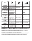
WARNING
: Improper switch position
may result in equipment damage.
-13-
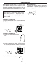
Installation of K691-10 Input Cable to Power Sources with a
14-pin Connector
1. Identify the cable end which has a 115V cordset with plug
attached to the Amphenol connector. This end attaches to
the engine-driven power source.
2. Connect the gas line to the gas cylinder regulator, connect
the electrode cable to the positive (+) output stud on the
power source, connect the control cable to the 14-pin
Amphenol connector on the power source (if present), and
plug the 115V plug into the outlet for 115V auxilliary power.
3. At the other end of the cable, attach the control cable
Amphenol connector, gas line connector, and electrode
cable terminal to their respective connectors on the rear
panel of the control module.
4. Set the Mode Switch on back of the Control Module for the
type of contactor circuit in the power source being used.
See “Setting the Mode Switch on Rear Panel”.
WARNING
: Improper switch position may result in equip-
ment damage.
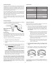
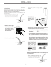
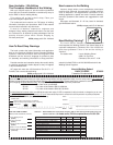
Setting the Mode Switch on Rear Panel
The slide switch on the rear panel selects between power
sources whose output contactors
are either internally energized or
externally energized from 115 VAC.
The Control Module is shipped
with the mode switch in the left
switch position and is for power
sources requiring only circuit clo-
sure (i.e., continuity) to energize
the output contactor. Lincoln ma-
chines are of this type. Right switch
position is for power sources re-
quiring that 115 VAC be supplied to
the contactor.
Make appropriate
power source
connections
and