


– 10 –
INSTALLATION
Safety Precautions
• Connect the Idealarc 250 grounding terminal located
under the reconnect panel (marked ) to a good
electrical ground per the U.S. National Electrical
Code and any applicable local codes.
• Turn the power switch on the Idealarc 250 “OFF”
before connecting or disconnecting output cables or
other equipment.
• Only qualified personnel should perform this installa-
tion.
Undercarriages
: If the optional K866 undercarriage
is to be installed, it should be done before connecting
the welder to power lines. Instructions are included
with the undercarriage.
ELECTRIC SHOCK can kill.
• Do not touch electrically live parts or
electrode with skin or wet clothing.
• Insulate yourself from work and
ground.
• Always wear dry insulating gloves.
------------------------------------------------------------------------
FUMES AND GASES can be dangerous.
• Keep your head out of fumes.
• Use ventilation or exhaust to remove
fumes from breathing zone.
------------------------------------------------------------------------
WELDING SPARKS can cause fire or
explosion.
• Keep flammable material away.
• Do not weld on closed containers.
------------------------------------------------------------------------
ARC RAYS can burn eyes and skin.
• Wear eye, ear and body
protection.
------------------------------------------------------------
See additional warning information at the
front of this operatorʼs manual.
-----------------------------------------------------------
WARNING
Location
The machine should be located in a clean, dry place
where there is free circulation of clean air such that air
movement in the back and along the sides will not be
restricted. Dirt and dust that can be drawn into the
machine should be kept to a minimum. Failure to
observe the precautions can result in excessive
operating temperatures and nuisance shutdown of the
machine.
Input Connections
Be sure the voltage, phase and frequency of the input
power is as specified on the welder rating plate locat-
ed on the rear panel of the machine. Either a single
phase or one phase of a three phase line can be
used.
Have a qualified electrician install the machine per the
following instructions:
Remove the left side panel (viewed from the front).
Route the input power lines through the hole in the
rear panel and center baffle. Lug the input leads with
a ring terminal for a 1/4” (6mm) screw. Connect
lugged leads to L1 and L2 of the reconnect panel per
the wiring diagram pasted to m inside of the side
panel. Input connection must conform to the U.S.
National Electrical Code and all local codes.
Models designed for two or three input voltages are
shipped connected for the highest voltage.
Reconnect instructions are on the diagram pasted to
the inside of the side panel. Consult rating plate on
the rear panel for machine input voltage rating.
The welder frame must be grounded. A stud marked
with the symbol located under the reconnect
panel is provided for this purpose. See the U.S.
National Electrical Code for details on proper ground-
ing methods.
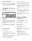
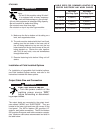
Fuse the input circuit with the recommended super lag
fuses. Choose an input and grounding wire size accord-
ing to local codes or use the following table. “Delay type”
circuit breakers may be used in place of fuses. Using
fuses or circuit breakers smaller than recommended may
result in “nuisance” tripping from welder inrush currents
even if not welding at high currents.
200 50/60 58 81 #8 #6 #8 70 100
208 60 55 77 #8 #6 #8 70 100
220/230 50/60 50 70 #8 #6 #8 70 90
380 50 29 41 #10 #8 #10 40 50
400 50/60 29 40 #10 #8 #10 40 50
440/460 50/60 25 35 #12 #10 #10 35 45
500 50 22 31 #14 #12 #10 30 40
575 60 20 28 #14 #12 #10 25 40
Input
Volts
Freq.
With
P.F.
Cap
Without
P.F.
Cap
With
Cap
Without
Cap
Grounding
Conductor
With
P.F.
Cap
Without
P.F.
Cap
Input Amps
Copper Wire Sizes
75°C in Conduit
Fuse Size
(Super Lag)
RECOMMENDED INPUT WIRE, GROUND WIRE AND FUSE SIZES 200 Amp Output and 50% Duty Cycle