


TROUBLESHOOTING
E-6 E-6
SQUARE WAVE TIG 355
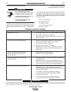
TROUBLESHOOTING GUIDE Observe Safety Guidelines
detailed throughout this manual.
ACCESSORIES
SYMPTOM CAUSE AND REMEDY
K870 Foot Amptrol or K963 Hand Amptrol.
Amptrol does not control welder output with 1. Check continuity between pins D and E in the cable connec-
Current Control switch in REMOTE and tor. There should be an open circuit when the Amptrol is not
Mode switch in TIG. pressed and a short circuit when it is pressed part way. If this
is not the case, check the Amptrol cable for breaks. The
microswitch in the Amptrol may not be operating properly.
Repair or replace as necessary.
2. Using an ohmmeter, check the resistance between pins A
and B in the Amphenol connector. The resistance should be
10K ohms when the pedal is up, and near zero ohms when
the pedal is fully depressed. An open circuit would indicate a
bad cable or defective potentiometer. Check for breaks and
repair or replace the damaged cable or potentiometer.
K814 Arc Start Switch
Arc Start Switch does not start welder output 1. Check continuity between pins D and E of the cable
in TIG Mode and LOCAL Current Control. connector. There should be an open circuit when the switch
is not pressed, and a short circuit when the switch is
pressed.
Check the cable for breaks, and repair or replace as
necessary. Check the switch and its connections.
2. Be sure the 2-Step/4-Step Switch is set correctly.
K846 Interface Kit
Solid State Relay Module output does not close 1. Is the correct type of solid state relay module installed? AC
when corresponding Status PC board LED lights. modules work only for AC circuits, and DC modules only for
DC circuits.
2. Is the corresponding fuse (F1 for CR1, F2 for CR2, etc.)
blown? If so, find cause and replace with a 4 amp fuse.
3. Are the Interface and Status PC boards correctly mated to
one another? Be sure that all 10 pins on P701 are inserted
into J602 on the Status PC board.
4. Is harness connector P601 plugged into J701 on the
Interface PC board?
5. Is Terminal Strip (TS701) wired correctly (terminals 3 and 4
for CR1, terminals 5 and 6 for CR2, etc.)?
6. Is DC polarity of terminal strip connection correct? Odd num-
bers (+), even numbers (–).
7. Defective solid state relay. Replace.
Solid State Relay Module output seems to 1. High Frequency pickup may be a problem. Reroute leads
make contact at wrong times. going to Interface terminal strip away from welding cables
which carry high frequency.
2. Use shielded cables to make connections to the Interface PC
board terminal strip. Ground the shield to terminal 1 or 2 on
TS701.
3. Be sure that the white ground lead is on the Interface PC
board tab terminal and is connected to the welder chassis
screw.