


B-2
OPERATION
B-2
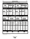
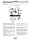
1. Power Switch - Place the lever in the “ON” position to
energize the machine. When the power is on, the fan will
operate and the output will be energized in SMAW
modes. GTAW mode requires remote trigger to energize
the output.
2. Output Control - This controls the output current. Control
is provided over the entire output range of the power
source with 1 turn of the control knob. This control may
be adjusted while under load to change power source
output. When using remote control this function becomes
the limit setting.
3. Local/Remote Switch - Place in the “LOCAL” position to
allow output adjustment at the machine. Place in the
“REMOTE” position to allow output adjustment at remote
pot or amptrol. In Remote, the machine output control pot
is the limit setting for remote control.
4. Mode Switch
GTAW Optimized for touch start use. Triggering at
amphenol is required using an Arc Start Switch, Amptrol
or similar means. Short circuit current is limited to approx-
imately 25 amps to aid in touch starting.
CC Soft Best for EXX18 thru EXX28 stick electrodes.
Output energized when machine is on.
CC CrispUse this mode for stick welding with EXX10
thru EXX14 electrodes. Output energized when machine
is on.
5. Hot Start - Controls the amount of starting energy in
SMAW. The Hot Start setting will set the amount of extra
power given during the initial strike.
A Hot Start setting of 100% will give you an additional
striking current 100% above the welding set current*.
(Striking current in this example will be 200% of the set
current). For a Hot Start setting of 100%, the current will
decrease back to the set current in one second.
A Hot Start setting of 50% will give you an additional
striking current 50% above the welding set current*.
(Striking current in this example will be 150% of the set
current). For a Hot Start setting of 50%, the current will
decrease back to the set current in .5 second.
* The maximum striking current is 300 Amps.
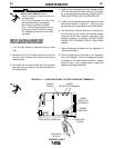
INVERTEC V250-S
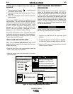
CONTROLS AND SETTINGS
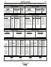
All operator controls and adjustments are located on the case front of the V250-S. Refer to Figure B.1 and corre-
sponding explanations.
FIGURE B.1 — CASE FRONT CONTROLS.
O
I
INVERTEC V250-S
®
S
-
+
1
15
50
85
120
170
230
250
A
OUTPUT
SMAW
SOFT
GTAW
SMAW
CRISP
REMOTE
LOCAL
THERMAL
HOT START
1
2
3
4
6
7
8
9
10
5
0
ARC FORCE
1
2
3
4
6
7
8
9
10
5
0
1
2
3
4
5
6
7
8