


A-9
INSTALLATION
SYNERGIC 7F & FH
A-9
ELECTRICAL INSTALLATION
Input Cable: Synergic 7F Control to Power Wave
Synergic Type Power Sources
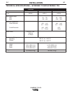
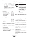
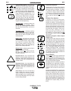
NOTE: CSAnrtl certification of the Synergic 7 models is with
input cable assemblies identified by carton date codes
010161, or above. These assemblies have grounding lead
continituity between the 14-pin plug pin B and the 8-socket
plug pin E per diagram below.
K648 - (Used with Power Wave 450) Consists of an 8-con-
ductor control cable with a 14-pin plug and a 4/0 (107 mm
2
)
electrode cable with stud terminal. It is rated at 500 amps,
60% duty cycle and is available in lengths of 7 ft (2 m), 17 ft
(5 m), 25 ft (7.6 m), 33 ft (10 m) and 50 ft (15 m).
K649 - (Used with Power Wave 450/500)
Consists of an 8-
conductor control cable with a 14-pin control cable plug and a
4/0 (107mm
2
) electrode cable with Twist-Mate™ connector. It
is rated at 500 amps, 60% duty cycle and is available in lengths
of 7 ft (2 m), 17 ft (5 m),
25 ft (7.6 m),
33 ft (10 m) and 50 ft (15
m).
K642 (Control Cable Only) - Consists of an 8
conductor control cable with a 14-pin control cable
plug, without electrode cable, and is available in
lengths of 7 ft (2 m), 17 ft (5 m), 25 ft (7.6 m), 33 ft (10
m) and 50 ft (15 m).
K643 (Control Cable Extension) - Consists of an 8
conductor control cable with 14-pin connectors on
each end for extending the control cable between the
power source and the control cables. Available in
lengths of 17 ft (5 m), 25 ft (8 m), 33 ft (10 m) and 50
ft (15 m).
With input power disconnected from the power
source, install the input cable per connection diagram
S22015 in the rear of this manual and follow exactly
the instructions on the diagram or perform the follow-
ing:
1) Connect the end of the control cable with the 14-
pin cable plug to the mating receptacle on the
power source.
2) Connect the electrode lead of that same cable end
to the power source output terminal of the desired
polarity.
3) Connect the 14-socket plug of the control cable to
the mating receptacle on the bottom of the control
box.
4) If not using a single continuous electrode cable
from the Power Source to the Wire Feed Unit, bolt
the electrode lead from the power source to the
electrode lead to the wire feed unit using the nut
and bolt supplied with the K680 Control to Feed
Unit cable assembly. Insulate connection with elec-
trical tape.
Work Cable
Connect a work lead of sufficient size and length (per
the following table) between the proper output termi-
nal on the power source and the work. Be sure the
connection to the work makes tight metal-to-metal
electrical contact.
* For pulse welding applications, the next larger cable
size is recommended.
Copper Work Cable Size, AWG *
Up to 100 ft Length (30m)
Current
60% Duty
Cycle
300 Amps
400 Amps
500 Amps
00 (67 mm
2
)
000 (85 mm
2
)
000 (85 mm
2
)
WARNING
Observe all additional Safety Guidelines detailed
throughout this manual.
ELECTRIC SHOCK can kill.
• Do not touch electrically live parts such
as output terminals or internal wiring.
•
When inching with gun trigger, electrode and
drive mechanism are “hot” to work and
ground and could remain energized several
seconds after the gun trigger is released.
• Turn OFF input power at welding power
source before installation or changing
drive roll and/or guide tubes.
• Welding power source must be connected
to system ground per the National
Electrical Code or any applicable local
codes.
• Only qualified personnel should
perform this installation.
E=GND
8-PIN PLUG, FRONT VIEW
14-PIN PLUG, FRONT VIEW
B=GND