


A-7
INSTALLATION
LN-10 / ZIPLINE BOOM PACKAGE
A-7
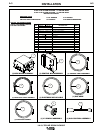
INSTALLATION PROCEDURE
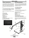
Assemble the Zipline boom according to the installa-
tion instructions provided with the boom. Next, install
and assemble the wire feeder boom package as fol-
lows:
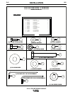
TOOLS REQUIRED
• 7/16" wrench
• 1/2" wrench
• 11/16" wrench
• 3/4" wrench
• Phillips head screwdriver
• Flat head screwdriver
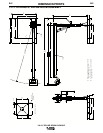
INSTALL THE WIRE DRIVE ASSEMBLY
With a 1/2" wrench, install the wire drive assembly
using the (4) 5/16-18 X .75 bolts and washers provid-
ed. Screw the bolts and washers partially into the bot-
tom of the wire drive assembly before placing the wire
drive assembly onto the feeder mount bracket & cage
assembly. After the wire drive assembly is in place,
completely tighten the bolts.
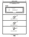
INSTALL THE CONTROL BOX ASSEMBLY
With a 7/16" wrench, install the control box assembly
using the (3) 1/4-20 X.75 bolts and washers provided.
Screw the bolts and washers partially into the control
box support before placing the control box assembly
onto the control box support. After the control box
assembly is in place, completely tighten the bolts.
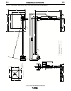
INSTALL THE POWER INPUT CABLE
ASSEMBLY
With a 3/4" wrench, install the 10' power input cable
assembly between the control box and the power
source. This assembly includes a control cable fas-
tened to a 3/0 weld cable. The pin end of the control
cable assembly connects to the power source. The
socket end of the control cable assembly connects to
the control box assembly. Install the user provided
electrode work cable between the power source and
work piece. Tighten all connections completely to
ensure a good electrical connection.
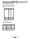
NOTE: The electrode weld cable provided with the
power input cable assembly is rated for 600 amps @
60 % duty cycle. If operating above this rating, an
additional cable should be used in parallel with the
cable provided.
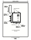
INSTALL THE ELECTRODE WELD CABLE
With a 3/4” wrench, install the single 3/0 electrode
weld cable between the wire drive assembly and the
control box assembly. The cable MUST
be routed
through the center of the boom arm steel tube.
Tighten all connections completely to ensure a good
electrical connection.
NOTE: The electrode weld cables provided with the
wire feeder boom package is rated for 600 amps @
60 % duty cycle. If operating above this rating, an
additional cable should be used in parallel with the
cable provided.
INSTALL THE CONTROL CABLE ASSEM-
BLY
Remove the trough cover on the top of the boom arm
assembly. Install the cable assembly between the wire
drive assembly and the control box assembly. The
pin end of the cable assembly connects to the control
box assembly. The socket end of the cable assembly
connects to the wire drive assembly. Neatly place the
cable in the trough and attach the cable to the control
box support using the supplied cable hangers.
Tighten all connections completely to ensure a good
electrical connection.
INSTALL THE GAS HOSE
With an 11/16” wrench, install the 25’ gas hose
between the wire drive assembly and a gas supply
connection. Neatly place the hose in the trough.
Tighten connections completely to ensure a good gas
connection.