


D-5
MAINTENANCE
D-5
MAGNUM® 400 FM DUAL PROCEDURE GUNS
SWITCH WIRES
T0 RED LEAD
CABLE ASSEMBLY
STRAIN RELIEF
STRAIN RELIEF
HOUSING
CABLE BOOT
GUN TUBE
TRIGGER WIRES
GUN HOUSING
TRIGGER ASSEMBLY
TO BLUE LEAD
SWITCH
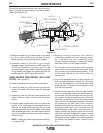
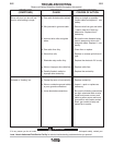
Figure E.6
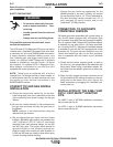
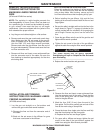
For K1723:
Connect the black lead and the white lead to the gun
trigger. Connect the other leads to the rocker switch
leads. (See Figure E.6).
j) Position the cable boot and strain relief on the cable
so it fits in cable handle cavity and lock the strain
relief in place by pushing the two halves together.
k) Assemble cable in left side of gun handle.
Assemble trigger into the proper handle cavity.(For
K1723 also assemble the rocker switch in the
groves provided in the handle.) Assemble right side
of gun handle and tighten the screws that hold the
handle together. (See Figures E.5 and E.6).
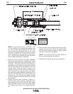
WIRE FEEDER END REPAIR (K575 AND
K1723) (See Figure E.7).
a) Remove the cable liner per previous instructions.
b) Loosen the boot nut. Slide the boot nut and boot
toward the middle of the cable past the damaged
section.
c) Rotate the collar nut until the screw anchoring the
cable handle is visible. Remove the screw and
save it.
d) Slide the cable handle and collar nut toward the
middle of the cable past the damaged section.
Remove the strain relief housing from the strain
relief and slide both toward the middle of the cable
past the damaged section. On older cables remove
and save the cable clamp that was used in place of
the strain relief.
NOTE: If sliding the cable handle becomes difficult,
try rotating it 180°.
e) Remove incoming connector from cable by
unscrewing connector nut from incoming connec-
tor. If the cable inner tube is difficult to remove
from the connector assembly, carefully slit it length-
wise with a knife up to the brass connector.
f) Cut the cable control wires where they meet the
cable jacket or else unsolder the connection where
they connect to the terminal lead assembly. If you
cut the wires, strip the cut end 1/4 inch (6.4 mm)
from the end.
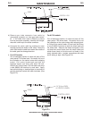
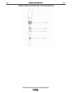
g) Cut off the damaged section of cable and strip off
the outer jacket as shown in Figure E.3. Be careful
not to cut the insulation on the control wires while
stripping jacket. Strip all four control leads 1/4 inch
(9.5 mm) from the end.
h) Check that the cable boot, boot nut, cable handle,
collar nut, strain relief, and strain relief housing are
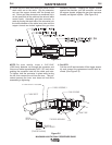
on the cable. Slip the connector nut over the cop-
per strands with the threaded end out. Orient the
connector assembly so the red and white control
leads will have the straightest possible routings to
the sockets on the back side of the connector.
Assemble the incoming connector to the cable by
forcing the steel tube of the connector into the
inside diameter of the cable inner tube until the
copper strands are butted against the incoming
connector shoulder. Keeping the copper strands
against the shoulder, pull the connector nut over
the copper strands, engage the incoming connec-
tor threads, and tighten in place. Refer to Figure
E.4.