


B-11
OPERATION
B-11
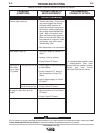
PRECISION TIG 375
Max. to Min.
Amptrol
Min. to Max.
Amptrol
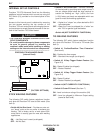
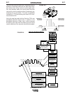
Setup for TIG Amptrol Welding
Advanced Panel
(If used)
Standard Controls
Power Switch
ON
Polarity Switch
AC or DC-
Mode Switch
TIG
AC Balance
AUTO
or
Set:
More + for alum.oxide "Cleaning"
w/o "Spitting" or "wetting" loss.
Balanced for equal
+
and
-
current.
More - for higher "Penetration".
Local/Remote
Switch
REMOTE
Trigger Switch
2-STEP
Pulse Switch
ON or OFF
Pulse Frequency
4-6 pps is a typical initial setting.
Set for bead shape and travel speed:
Higher for thinner plate and faster travel.
Lower for thicker plate and slower travel.
% On Time
40-60% is a typical initial setting.
Set for total heat of Peak current:
Lower reduces distortion and burn-thru.
Background Current
40-60% is a typical initial setting.
Set as low as will maintain a pulse arc
(Will not drop below
Min.Output
setting.)
Downslope
ZERO
For no arc-out delay.
Minimum Output
Press Display switch
and Set to desired min.
Amptrol (Start/Crater)
output level.
Postflow
Set as low as required.
Higher for larger
tungsten and current.
Maximum Output
Set to desired max.
Amptrol output level.
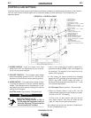
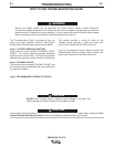
FIGURE B.6
Controls
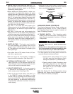
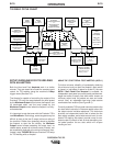
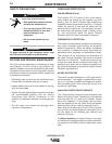
The new foot pedal provides such independent action
distinction of precisely where the arc start switch actu-
ates without over-riding minimum control pedal posi-
tion, and precisely where the control pedal has been
returned to minimum position without inadvertently de-
actuating the arc start switch. The result is repeatable
consistency in TIG weld starting and crater-fill for man-
ual process control.
Using this new foot pedal with the Precision TIG’s new
presettable Minimum Output level, in addition to the
presettable Maximum Output level, further enhances
the starting and crater level consistency as well as the
control resolution of the manually controlled foot pedal.
Toe
Pressure
Switch
Foot
Rock
Control
Adjustable
or
Re
movable
H
eel Stop
Fully Pressed
Control Pedal
Maximum Output
Machine Setting
Minimum Output
Machine Setting
At-Rest
Control Pedal
Pressed
Switch Pedal
At-Rest
Switch Pedal
Off
Time
FIGURE B.5