


A-12
INSTALLATION
POWER WAVE 455/STT
A-12
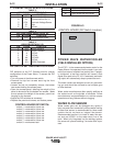
I / O RECEPTACLE SPECIFICATIONS
TABLE 3
WIRE FEEDER RECEPTACLE S1
PIN LEAD# FUNCTION
A 53 Communication Bus L
B 54 Communication Bus H
C 67A Electrode Voltage Sense
D 52 0vdc
E 51 +40vdc
TABLE 4
VOLTAGE SENSE RECEPTACLE S2
PIN LEAD# FUNCTION
3 21A Work Voltage Sense
TABLE 5
RS232 RECEPTACLE S3
PIN LEAD# FUNCTION
2 253 RS232 Receive
3 254 RS232 Transmit
4 # S3 Pin5
5 # S3 Pin4
6 # # S3 Pin20
20 # # S3 Pin6
7 251 RS232 Commom
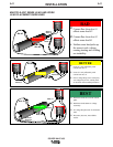
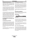
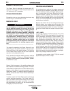
DIP SWITCH SETTINGS AND LOCATIONS
DIP switches on the P.C. Boards allow for custom
configuration of the Power Wave. To access the DIP
switches:
• Turn off power at the disconnect switch.
• Remove the top four screws securing the front
access panel.
• Loosen, but do not completely remove, the bottom
two screws holding the access panel.
• Open the access panel, allowing the weight of the
panel to be carried by the bottom two screws. Make
sure to prevent the weight of the access panel from
hanging on the harness.
• Adjust the DIP switches as necessary.
• Replace the panel and screws, and restore power.
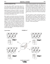
CONTROL BOARD DIP SWITCH:
switch 1 = reserved for future use
switch 2 = reserved for future use
switch 3 = reserved for future use
switch 4 = reserved for future use
switch 5 = reserved for future use
switch 6 = reserved for future use
switch 7 = reserved for future use
switch 8 = work sense lead
switch 8
work sense lead
off work sense lead not connected
on work sense lead connected
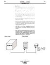
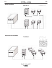
POWER WAVE WATERCOOLER
(FIELD INSTALLED OPTION)
The K1767-1 is the recommended water cooler for the
Power Waves. Incorporated into the cooler is an auto-
matic flow sensor to detect low coolant flow. If proper-
ly configured, a low flow condition will cause a fault
signal to be sent to the PF-10/11 feed head, and weld-
ing output will automatically stop to protect the torch.
The water coolers are designed to cool only one weld-
ing gun and should be not used to cool multiple guns
or other devices.
Water cooler manufacturers often specify additives to
the coolant such as fungicides or alkalides. Follow
manufacturers recommendations to achieve proper
operation and long lifetimes without clogging.
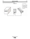
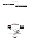
WATER FLOW SENSOR
Water cooled guns can be damaged very quickly if
they are used even momentarily without water flowing.
A water flow sensor is recommended for those water
coolers that do not have an integral flow sensor.
Recommended practice is to install a water flow sen-
sor such as K1536-1 on the water return line of the
torch. When fully integrated into the welding system,
the sensor will prevent welding if no water flow is pre-
sent.
CONTROL BOARD (DIP Switch Location)
FIGURE A.3