


A-3
INSTALLATION
A-3
INVERTEC® V350-PRO (CE)
LN-15 Connection Instructions
• Turn the Invertec
®
power switch "off".
• Connect the electrode cable to the output terminal of
polarity required by electrode. (See Figures below)
• Set the meter polarity switch on the front of the Invertec
®
to coincide with wire feeder polarity used.
LN-25 Connection Instructions
• Turn the Invertec
®
power switch "off".
• Connect the electrode cable to the output terminal of
polarity required by electrode. Connect the work lead to
the other terminal.
• LN-25 with Remote Control options can be used with the
"CE" version of the V350. The 6-Pin (K444-1) and 14-pin
(K444-2) remotes can be connected directly to the 6-pin
& 14-pin MS-style connector. The 42 Volt Remote
Voltage and Output Control (K624-1) Kit can be connect-
ed to the V350’s 14-pin MS-style connector using
Remote Control Cable assembly K627- [ ]. LN-25s with a
K431-1 remote kit can be connected to the V350’s 14-pin
MS-style connector using a K432 cable and K876
adapter. (See connection diagram S19899). Or the K432
cable could be modified with a K867 Universal Adapter
Plug (See connection diagram S19405) to connect it to
the V350’s 14-pin MS-style connector.
LN-742 Connection Instructions
• Turn the Invertec
®
power switch "off"
• Either a K591 or a K593 Input cable assembly is
required to connect the LN-742 to the Invertec
®
.
• Connect the control cable from the LN-742 to the
14-pin MS-style connector
.
• Connect the electrode cable to the output terminal
of the polarity required by electrode. Connect the
work lead to the other terminal.
• Set the meter polarity switch on the front of the
Invertec
®
to coincide with wire feeder polarity used.
The wire feeder will now display the welding volt-
age.
• If a remote control such as K857 is to be used with
the LN-742, the remote can be connected directly
to the
6-pin MS-style connector
on the front of the
Invertec
®
or use a K864 adapter to connect the LN-
742 and the remote to the
14-pin MS-style connector
.
Cobramatic Connection Instructions
• Turn the Invertec
®
power switch "off"
• Connect the control cable from the Cobramatic to
the
14-pin MS-style connector
.
• Connect the electrode cable to the output terminal
of the polarity required by electrode. Connect the
work lead to the other terminal.
• Set the meter polarity switch on the front of the
Invertec
®
to coincide with wire feeder polarity
used.
• If a remote control such as K857 is to be used
with the Cobramatic, the remote can be connected
directly to the
6-pin MS-style connector
on the front
of the Invertec
®
or use a K864 adapter to connect
the cobramatic and the remote to the
14-pin MS-
style connector
.
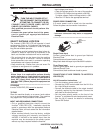
CONNECTION OF WIRE FEEDERS TO V350-PRO (CE)
Wire feeders other than these listed may be used pro-
vided that the auxiliary power supply capacity of the
Invertec
®
is not exceeded. K867 Universal Adapter
Plug may be required. See connection diagram
S24985 on page F-4.
REMOTE CONTROL OF INVERTEC
®
Remote Control K857, Hand Amptrol K963 and Foot
Amptrol K870.
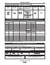
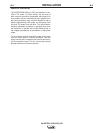
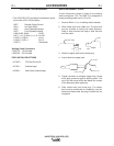
UNDERCARRIAGE MOUNTINGS
1
4.7
9
1
2.44
3.44
2
1.60
2
7.82
5.50
10.00
MOUNTING HOLE LOCATIONS
M19527
13.1
0
1/4-20 NUT (4 PLACES)
NOTE: MOUNTING SCREWS CA
4/01
N NOT PROTR
UDE MORE THAN
0.5 IN
CHES INSIDE THE MACHINE.
11.8
4
3.50
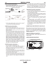
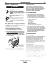
Work
Clamp
Electrode Cable
E
lectrode Cable
Electrode Cable
W
ork
Clamp
Work
Clamp
wire feeder
K
1870-1
wire feeder
K
1870-1
RANGER 8
SAE 400 WITH CV ADAPTER
ENGINE DRIVEN WELDERS
WITH WIRE FEED MODULE
(LOCAL MODE AND CV ADAPTER)
CV250
CV300
CV400
CC POWER SOURCE
Output Terminals
A
lways Hot.
Output Terminals
Always Hot.
Output Terminals
A
lways Hot.
Order K484 Jumper
P
lug Kit.
Electrode Cable
Work
Clamp
semiautomatic
s
emiautomatic
semiautomatic
semiautomatic
w
ire feeder
K1870-1
w
ire feeder
K1870-1
wire feeder
K1870-1
CV655, DC400, DC600,
DC655, V350-PRO,
RANGER 9, RANGER 300 DLX
COMMANDER 300
COMMANDER 500
RANGER 2V35050
RANGER 305G
Output TerminalsOutput Terminals
Always Hot.Always Hot.
Power source contactorPower source contactor
switch must be in theswitch must be in the
"ON" position or use a "ON" position or use a
K848 Junper Plug Kit.K848 Junper Plug Kit.
ACROSS THE ARC MODEL
V
350-PRO
T
WIST-MATE
CONTROL CABLE MODEL
Electrode Cable