


A-2
A-2
INSTALLATION
SAFETY PRECAUTIONS
Read entire installation section before starting
installation.
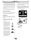
IDENTIFY AND LOCATE
COMPONENTS
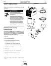
If you have not already done so, unpack the SP-170T
from its carton and remove all packing material
around the SP-170T. Remove the following loose
items from the carton (see Figure A.1):
1. SP-170T
2. Gun and cable assembly
(1)
3. Literature and miscellaneous including:
a) This operating manual
b) A separate .030" (0.8 mm) contact tip
c) Hex key wrench for removal of drive roll.
4. 10 ft (3,0 m) work cable.
5. Work clamp.
6. 2lb. Spool of Super Arc L-56 .025 MIG Wire.
7. Adjustable mixed-Gas Regulator & Hose.
(1)
The gun is ready to feed .023" – .025" diameter
wire.
ELECTRIC SHOCK can kill.
• Only qualified personnel should perform
this installation.
• Only personnel that have read and under-
stood the SP-170T Operating Manual
should install and operate this equipment.
• Machine must be plugged into a receptacle
which is grounded per any national, local
or other applicable electrical codes.
• The SP-170T power switch is to be in the
OFF (“O”) position when installing work
cable and gun and when connecting power
cord to input power.
WARNING
FIGURE A.1
1
2
3
4
5
W
E
L
D
I
N
G
A
M
P
R
A
N
G
E
WELDING AMP
RA
N
G
E
2
5
-
12
5
25-125
6
7
SP-170T