


ES 275i
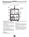
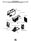
OUTPUT CONNECTIONS
Refer to figure B.1 for the location of the 3-Pin
Remote Receptacle and the Output Terminals.
OUTPUT CABLES
Select the output cable size based on Table A.1.
TABLE A.1
Cable Sizes for Combined Length of Electrode and
Work Cable ( Copper Cable Rated at 75°C).
Length Cable Size
up to 150 ft.(46m) 1/0 (50mm
2
)
up to 250 ft.(72m) 2/0 (70mm
2
)
A-3
INSTALLATION
A-3
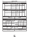
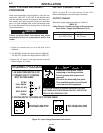
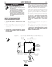
INPUT VOLTAGE RECONNECT
PROCEDURE
When received directly from the factory, units are con-
nected for, 460 VAC. If 460 VAC is the desired input,
then the machine may be connected to the power sys-
tem without any setup required inside the reconnect
door. For other voltages refer to the instructions locat-
ed on the Reconnect Panel Access Door or follow the
instructions below.
Failure to follow these instructions can cause
immediate failure of components within the
welder.
------------------------------------------------------------------------
1. Open the access door on the left side of the
machine.
2. For 208-230: Position the large switch to 208-230.
For 380-575: Position the large switch to 380-575.
3. Move the “A” lead to the appropriate terminal.
Refer to figure A.1 below.
.
.
.
.
Do not touch electrically live parts.
Only qualified persons should install,
use or service this equipment.
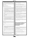
RECONNECT PROCEDURE
1. BE SURE POWER SWITCH IS OFF.
208V
220-230V
380-415V
440-460V
575V
'A'
INPUT VOLTAGE RANGE.
removed.
Do not operate with wraparound
inspecting or servicing machine.
Disconnect input power before
IF MACHINE CEASES TO OPERATE (NO METER, NO FAN)
2. CONNECT LEAD 'A' TO DESIRED
3. POSITION SWITCH TO DESIRED INPUT VOLTAGE RANGE.
AND THERE IS NO OTHER KNOWN FAILURE: CHECK FUSE;
VOLTAGE=380-575V
VOLTAGE=208-230V
REPLACE WITH SPECIFIED FUSE.
Figure A.1 Input Voltage Reconnect Instructions
CAUTION