


A-4
INSTALLATION
LN-35
A-4
WELD CABLE CONNECTION
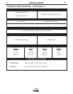
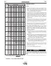
The size of the electrode cable and work cable must
be sufficient for the maximum weld current and total
cable length to be used. Refer to table A.1.
TABLE A.1
Total Cable Length
Weld Current
60% Duty Cycle 50’-100’ 100’-150’ 150’-200’ 200’-250’
200Amps 2 AWG 2 AWG 1 AWG 1/0
300Amps 1 AWG 1 AWG 1/0 2/0
400Amps 2/0 2/0 3/0 3/0
500Amps 2/0 3/0 3/0 4/0
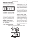
ELECTRODE CABLE CONNECTION
Route the electrode cable through the oval hole in
the LN-35 rear panel. Connect the electrode cable to
the LN-35 using the
1
2” bolt on the front of the wire
drive.
WORK CABLE CONNECTION
Connect a work lead of sufficient size between
the proper output stud on the power source and
the work. Be sure the connection to the work
makes tight metal-to-metal electrical contact.
Poor work lead connections can result in poor
welding performance.
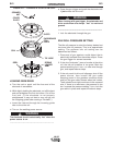
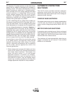
DRIVE ROLL INSTALLATION
CHANGING DRIVE ROLLS FOR TWO-
ROLL WIRE FEEDERS:
To change drive rolls on a two-roll wire feeder, refer
to Figure A.1 and perform the following steps:
1. Rotate the latch knob on the quick release
arm.
2. Remove the hex head screw and clamping
collar. Remove the drive roll from the shaft.
3. The new roll to be installed is stamped for the
size to be fed. An “A” after the size indicates
aluminum wire. Remove the rolls from the kit and
wipe them clean. Wipe the output shaft and
locating shoulder clean.
4. Use the drive key, clamping collar, and hex
head screw to install the roll on the output shaft.
Certain size drive rolls consist of two roll halves,
and may contain a spacer. If the drive roll you
are installing contains a spacer, the spacer fits
between the two halves of the drive roll. Tighten
the hex head screw.
5. Back out the guide tube clamping screws.
Remove the old guide tubes, if installed.
6. Insert the outgoing guide tube (the one with
the plastic insert) into the front hole. If the
guide tube has a non-symmetrical chisel end,
the larger radius must face the drive roll. See
Figure A.1. Push the guide tube back as far
as it will go and tighten the clamping screw.
Insert the incoming guide tube as far back as
it will go and tighten the clamping screw. The
clamping screws are dog points. When the
guide tubes are properly installed these dog
points will lock into the annular grooves in
each of the guide tubes.
7. Set the idle roll pressure as detailed in the Idle
Roll Pressure Setting procedure detailed later
in this section.
FIGURE A.1 – INSTALLING DRIVE ROLLS ON A TWO-ROLL FEEDER.