


B-2
OPERATION
B-2
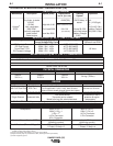
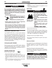
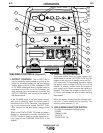
WELDING CONTROLS (Figure B.1)
1. OUTPUT CONTROL:
The OUTPUT dial is
used to preset the output voltage or current as dis-
played on the digital meters for the four welding
modes. When in the CC-STICK, DOWNHILL PIPE
or CV-WIRE modes and when a remote control is
connected to the 6-Pin or 14-Pin Connector, the
auto-sensing circuit automatically switches the
OUTPUT CONTROL from control at the welder to
the remote control.
In the CV-WIRE mode, if the wire feeder has volt-
age control capability, when the control cable is
connected to the 14-Pin Connector, the auto-sens-
ing circuit automatically makes OUTPUT CON-
TROL inactive and the wire feeder voltage control
active.
When in the TOUCH START TIG mode and when a
Amptrol is connected to the 6-Pin Connector, the
OUTPUT control is used to set the maximum cur-
rent range of the CURRENT CONTROL of the
Amptrol.
2. DIGITAL OUTPUT METERS
The digital meters allow the output voltage (CV-
WIRE mode) or current (CC-STICK, PIPE and TIG
modes) to be set prior to welding using the OUT-
PUT control dial. During welding, the meter display
the actual output voltage (VOLTS) and current
(AMPS). A memory feature holds the display of
both meters on for seven seconds after welding is
stopped. This allows the operator to read the actu-
al current and voltage just prior to when welding
was ceased.
While the display is being held the left-most deci-
mal point in each display will be flashing. The
accuracy of the meters is +/- 3%.
3. WELD MODE SELECTOR SWITCH:
(Provides four selectable welding modes)
CV-WIRE
DOWNHILL PIPE
CC-STICK
TOUCH START TIG
RANGER 305D (CE)
1
10
7
4
9
5
8
11
12
13
6
15
14
17
16
2
3
FIGURE B.1