


'&.).-$S*7?;GFA?3F;5&B7D3F;A@
Power Wave 405M can only be used with D5#;@=
5A?B3F;4>7'AI7D776$ semi-automatic wire feed-
ers. In addition, the Power Feed M semi-automatic
wire feeders may require optional equipment to
access certain weld modes in the Power Wave. Other
models of Lincoln feeders, or any models of non-
Lincoln wire feeders, cannot be used.
All welding programs and procedures are selected
through the Power Feed M semi-automatic user inter-
face
)(, )(, '$%+
Any ArcLink compatible semi-automatic wire feeding
equipment. Specifically, the semi-automatic Power
Feed M family.
# $ ++ &%*
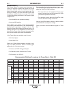
• Only D5#;@=5A?B3F;4>7'AI7D776$ semi-
automatic wire feeders and users interfaces may be
used. Other Lincoln wire feeders or non-Lincoln wire
feeders cannot be used.
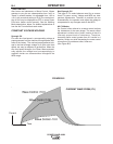
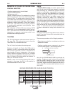
• POWER WAVE 405M Output Limitations
The POWER WAVE 405M will support maximum
average output current of 350 Amps @ 60% duty
cycle.
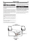
,+00#%+ $') &
The duty cycle is based upon a ten minute period. A
60% duty cycle represents 6 minutes of welding and 4
minutes of idling in a ten minute period.
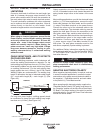
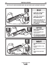
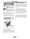
*)&%+&%+)&#*
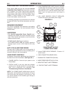
All operator controls and adjustments are located on
the case front of the Power Wave. *77;9GD7
1. POWER SWITCH: Controls input power to the
Power Wave.
2. STATUS LIGHT: A two color light that indicates
system errors. Normal operation is a steady green
light. Error conditions are indicated, B7D
+DAG4>7E:AAF;@9*75F;A@;@F:;E$3@G3>
%&+The POWER WAVE 405M status light will
flash green, and sometimes red and green, for up to
one minute when the machine is first turned on. This
is a normal situation as the machine goes through a
self test at power up.
&')+ &%
'&.).-$
,)
3. HIGH TEMPERATURE LIGHT (thermal overload):
A yellow light that comes on when an over temper-
ature situation occurs. Output is disabled and the
fan continues to run, until the machine cools down.
When cool, the light goes out and output is
enabled.
4. CB1 WIRE FEEDER CIRCUIT BREAKER:
Protects 40 volt DC wire feeder power supply.
10
4
6
1
3
2
5
7
8
9
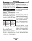
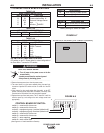
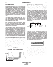
*)&%+#0&,+
'&.).-$
5.
Internal POWER CIRCUIT BREAKER:
Protects 115
volt AC circuit.
6. LEAD CONNECTOR (SENSE LEAD)
7. DIAGNOSTIC CONNECTOR (RS-232)
8. WIRE FEEDER RECEPTACLE (5-PIN)
9. NEGATIVE TWIST- MATE TERMINAL
10. POSITIVE TWIST- MATE TERMINAL