


B-6
OPERATION
B-6
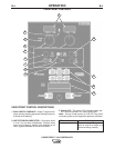
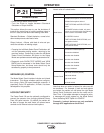
WELD MODE DESCRIPTION
1. Allows wireless machine configuration using a Palm
OS based hand-held computer.
2. Consists of easy to read 36 segment alphanumeric
LED display.
2 Thru 5 Allows for machine set-up/user preferences
grouped into secure and non-secure categories.
6.- 7. Provides easy access to the multiple weld pro-
grams inside the Power Wave power sources.
Pushbutton selection for setting AC parameters.
8. Primarily used to change the value of the selected
attributes.
9.- 10. Provide complete control of the starting and
ending sequence. Pushbutton for selecting
welding program and parameters.
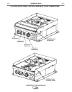
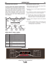
POWER FEED™ 10A CONTROLLER
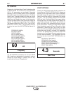
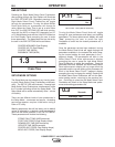
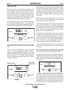
CHANGING WELD MODES
To select a weld mode, press the left Mode Select
Panel pushbutton(7) until the WELD MODE LED(6) is
illuminated (it may be illuminated by default at power
up). Turn the Mode Select Panel Knob(8) until the
desired weld mode number(2) is displayed. As the
Mode Select Panel Knob is rotated, only the weld
mode number is displayed. After 1 second of knob
idle time, the user interface will change to the selected
weld mode and the new mode’s welding parameters
will be displayed.
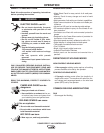
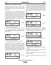
MODE SELECT PANEL 4 (MSP4)
ITEM DESCRIPTION
1 IR (Infrared) Port.
2 Weld Mode Number.
3 Weld Wire Type.
4 Wire Size.
5 Weld Mode Description.
6
Weld Mode/AC Control LED’s.
7 Selection Pushbutton Weld Mode or AC
Control.
8
“Set” (Adjustment) Dial / Knob
9
Selection Pushbutton Start and End
Option
10 Start/End Options
LED’s
.
START OPTIONS
END OPTIONS
SET
SETUP
IR PORT
CC 60Hz SIN WAVE
1/8"
STEEL
52
WELD MODE
AC CONTROL
2
1
3
4
5
6
10
7
8
9
C
C
6
0
H
z
S
I
N
W
A
V
E
CC 60 Hz SIN W
AV
E
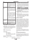
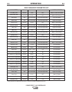
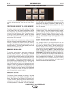
TABLE B.1 *
*This table is located on the inside of front panel door. This Chart will let the operator provide the proper Electrode, Wire size and Weld process for welding.