


MAGNUM 250 LX
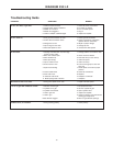
Troubleshooting Guide
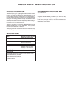
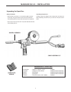
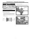
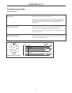
TESTING THE TORCH
Motor Check. Remove the torch connector from the cabinet.
Using the torch Control Cable Connector, check the resistance across pins “A”
and “B” (motor leads). The resistance across the motor should be between 5-10
ohms. If an open circuit or short exist, check the motor leads and motor
independently.
Testing the Potentiometer. Using the torch Control Cable Connector, check the resistance across pin “D”
(wiper) and pin “C”. The resistance should vary from 5K - 0 ohms.
Check the resistance across pin “D” (wiper) and pin “G”. The resistance should
vary from 5K - 0 ohms.
Testing the Trigger Switch. Using the torch Control Cable Connector, check for continuity across pins “E”
and “F” when the trigger is pressed.
11
A
B
C
D
E
G
F
"W" CLOCKED
CONNECTOR
(VIEWED FROM FRONT OF CONNECTOR)
A
B
G
D
F
E
TORCH
FUNCTIONS
+-
MOTOR
TORCH
C
POT
TORCH
13
2
5K
CW
TORCH
TRIGGER
RED
BLACK
WHITE
GREEN
BLUE
BROWN
YELLOW/ORANGE