


A-9
INSTALLATION
RANGER 250
A-9
CONNECTION OF LINCOLN ELEC-
TRIC WIRE FEEDERS
Connection of LN-7 or LN-8 to the RANGER 250
LPG
1. Shut the welder off.
2. Connect the LN-7 or LN-8 per instructions on the
appropriate connection diagram in Section F
3. Set the "WIRE FEEDER VOLTMETER" switch to
either "+" or "-" as required by the electrode being
used.
4. Set the "MODE" switch to the "CV WIRE " posi-
tion.
5. Set the "ARC CONTROL" knob to "0" initially and
adjust to suit.
6. Set the "WELD TERMINALS" switch to the
"REMOTELY CONTROLLED" position.
7. Set the "IDLE" switch to the "HIGH" position.
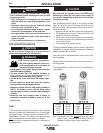
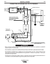
Connection of LN-15 Wire Feeder to the RANGER
250 LPG
These connections instructions apply to both the LN-
15 Across-The-Arc and Control Cable models. The
LN-15 has an internal contactor and the electrode is
not energized until the gun trigger is closed. When the
gun trigger is closed the wire will begin to feed and the
welding process is started.
a. Shut the welder off.
b. For electrode Positive, connect the electrode cable
to the "+" terminal of the welder and work cable to
the "-" terminal of the welder. For electrode
Negative, connect the electrode cable "-" terminal
of the welder and work cable to the "+" terminal of
the welder.
c. Across-The-Arc Model:
Attach the single lead from the front of the LN-
15 to work using the spring clip at the end of
the lead. This is a control lead to supply cur-
rent to the wire feeder motor; it does not carry
welding current.
Control Cable Model:
Connect Control Cable between Engine
Welder and Feeder.
d. Set the MODE switch to the "CV-WIRE " position.
e. Across-The-Arc Model:
Set the "WELD TERMINALS" switch to
"WELD TERMINALS ON"
Control Cable Model:
Set the "WELD TERMINALS" switch to
"REMOTELY CONTROLLED"
f. Set the "WIRE FEEDER VOLTMETER" switch to
either "+" or "-" as required by the electrode polarity
being used.
g. Set the "ARC CONTROL" knob to "0" initially and
adjust to suit.
h. Set the "IDLE" switch to the "AUTO IDLE" position.