


LN-25
C-3
Installation instructions (M17590) are included with
this kit.
K460-1 PULSE POWER ADAPTER KIT
(For use with K461 Pulse Power Control Cable.)
This kit enables the LN-25 to pulse weld with a Pulse
Power 500 power source above Code 9300 (or lower
Codes updated with S18506 Kit).
The kit includes a Remote PC board with output
voltage control, and control cable receptacle which
mount and connect inside the LN-25 control box
per the Installation Instructions (L9636) included with
the kit.
NOTE: If the K460-1 Pulse Power Adapter Kit is in-
stalled but the LN-25 is to be used without the K461
Pulse Power Control Cable Assembly, then the in-
structions for returning the unit to across the arc op-
eration included with the Installation Instructions
(L9636) must be followed.
K461 PULSE POWER CONTROL CABLE
ASSEMBLY
(Requires K460-1 Pulse Power Adapter Kit installed
in LN-25.)
The K461 control cable assemblies include an elec-
trode cable, rated for up to 500 amps 60% duty
cycle, and a 9-conductor control cable. The control
cable pin connector connects to the LN-25 and the
lugged leads connect to the Pulse Power. Available
in 25, 50, 75 and 100 ft. lengths.
K443-1 LN-25 CONTACTOR KIT
(Factory installed in K449 Model.)
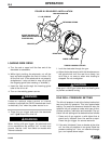
The internal contactor provides “cold” electrode until
the gun trigger is pressed, and a fixed burnback time
delay to prevent electrode from sticking in the weld
crater when the trigger is released. The contactor is
rated for use up to 300 amps. A cold inch switch
allows the wire to be loaded into the system without
being electrically “hot”.
Installation Instructions (L9676) are included with
the kit.
ACCESSORIES
NOTE: The K443-1 cannot be used with K431-1 or
K624-1 Remote Output Control Kit or K460-1 Pulse
Power Adapter Kit. If remote voltage control is
desired along with the internal contactor, obtain a
K444, K444-1 or K444-2 Remote Voltage Control Kit.
REMOTE OUTPUT CONTROL OPTIONS
AND CONTROL CABLE ASSEMBLIES
Remote Output Control Options are available to pro-
vide the LN-25 with the following additional features:
1. “Cold” electrode until the gun trigger is pressed,
and a fixed burnback time delay to prevent elec-
trode from sticking in the weld crater when the
gun trigger is released.
2. Remote (10K ohm rheostat) control of power
source output arc voltage level.
K431-1 REMOTE OUTPUT CONTROL KIT
(For use with K432 Remote Control Cable and K433
Power Source Remote Box.)
The Kit includes a Remote PC board and control
cable receptacle which mount and connect inside the
LN-25 control box per the Installation Instructions
(M17584) included with the kit.
NOTE: If the K431-1 Remote Output Control Kit is
installed but the LN-25 is to be used without the
K432 Remote Control Cable Assembly, then the Re-
mote Board harness plug must be removed from the
12-pin receptacle on the Control Board and the
jumper plug (T13498-21) reinstalled.
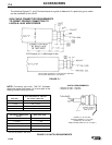
K433 POWER SOURCE REMOTE BOX
(Requires K431-1 Remote Output Control Kit installed
in LN-25 using K432 Remote Control Cable.)
The Remote Box is designed to mount and connect
to Lincoln Idealarc
®
semiautomatic power sources
per the Installation Instructions (M15324) and power
source connection diagrams included with the kit.
CAUTION
This kit can only be used with LN-25’s above Code
9200 or with LN-25’s equipped with a G1757-3 (or
higher part number) Control PC board. To prevent
possible damage to the LN-25 with internal
contactor, do not connect to non-Lincoln TIG or
Square Wave power sources. TIG high frequency
power should never be applied to the LN-25.