


B-3
OPERATION
B-3
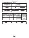
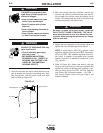
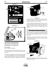
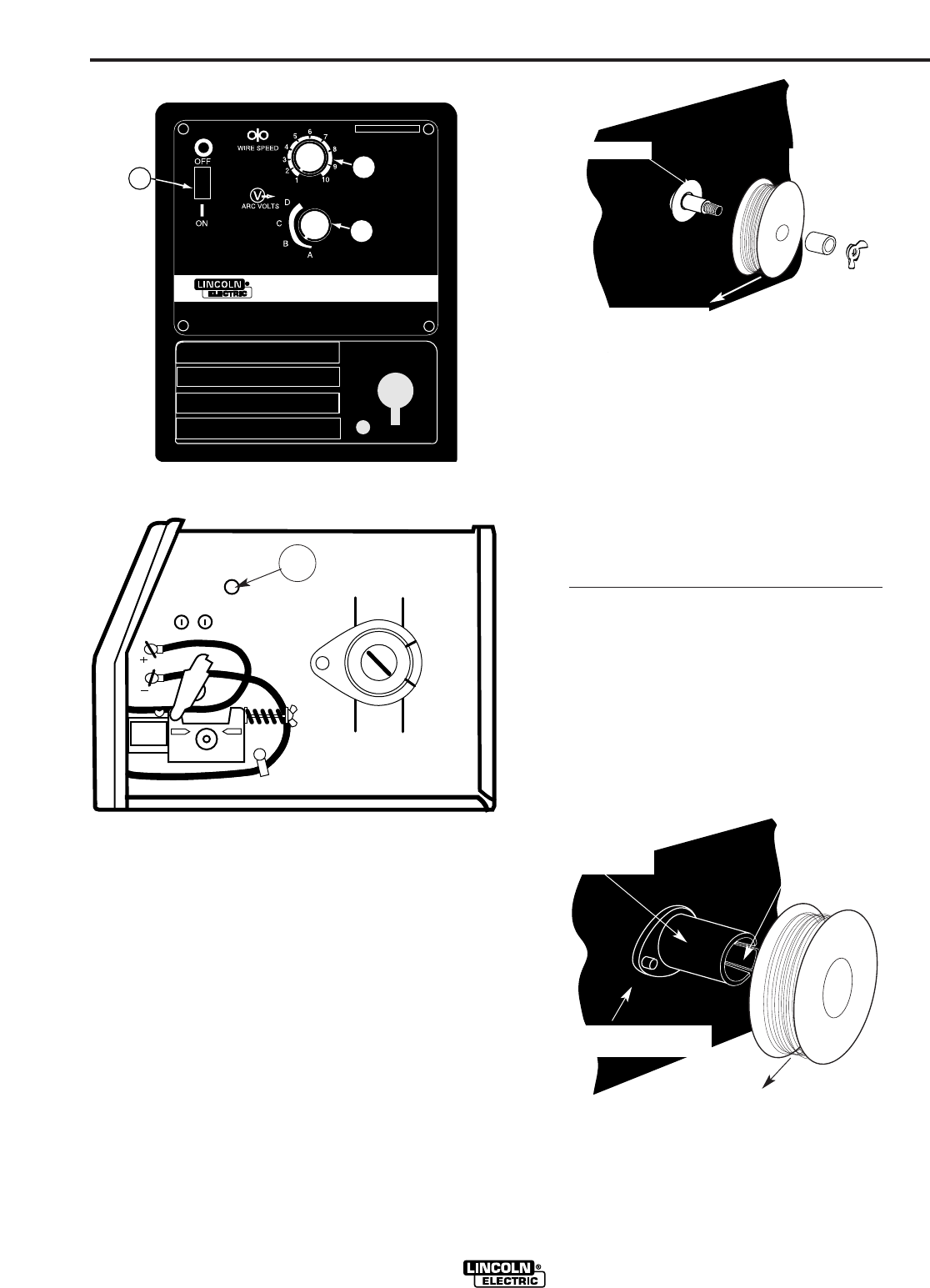
FIGURE B.1a
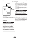
FIGURE B.1b
WELDING OPERATIONS
SEQUENCE OF OPERATION
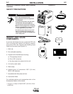
Wire Loading
Refer to Figure B.2 AND B3.
The machine power switch should be turned to the
OFF (“O”) position before working inside the wire feed
enclosure.
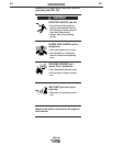
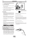
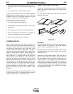
The machine is shipped from the factory ready to feed
4” (100 mm) diameter spools. A 4" (100 mm) diameter
spool is mounted directly on the 5/8" (16 mm) diame-
ter spindle that has a built-in adjustable friction brake
FIGURE B.2
to prevent overrun of the spool and excess slack in
the wire. The wing nut at the end of the shaft is used
to adjust the tension on the wire spool.
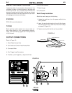
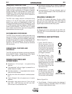
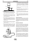
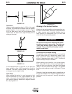
To use 8" (200 mm) diameter spools, the 2" (51 mm)
diameter M15445 spindle must be used. Remove the
spacer and wing nut at the end of the shaft. Insert
spindle as shown in figure B.3. Reattach spacer and
wing nut.
Note:When loading and removing the 8” Spools
make
sure that the wing nut (inside the wire spool spindle
hub) is turned 90° from the wire spool spindle locking
tab. If the wing nut is positioned in line with the locking
tab, the tab cannot be depressed to load or unload the
wire spool.
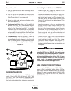
Make certain the start end of the wire, which may pro-
trude through the side of the spool, does not contact
any metallic case parts.
FIGURE B.3
PRO 100
PRO 100
DO NOT SWITCH
WHEN WELDING
3
2
1
Wire Spindle Shaft
4" Wire Spool
Wing Nut
and Spacer
Wire Spool must be pushed all the way on the spindle so that the
spindle’s tab will hold it in place. The Wire Spool will rotate clock-
wise when wire is dereeled.
8” Wire Spool
Optional
Wire Spool Spindle
Be sure that this stud engages
the hole in the wire spool.
To Wire Drive
4
Locking Tab
To wire drive