


E-10
TROUBLESHOOTING
E-10
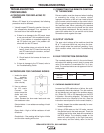
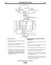
2. POWER DIODE TEST
a. Establish the polarity of the ohmmeter leads
and set to X10 scale.
b. Connect the ohmmeter positive lead to anode
and negative lead to the cathode.
c. Reverse the leads of the ohmmeter from Step
b.
d. A shorted diode will indicate zero or an equal-
ly low resistance in both directions. An open
diode will have an infinite or high resistance in
both directions, and a good diode will have a
low resistance in Step b and a much higher
resistance in Step c.
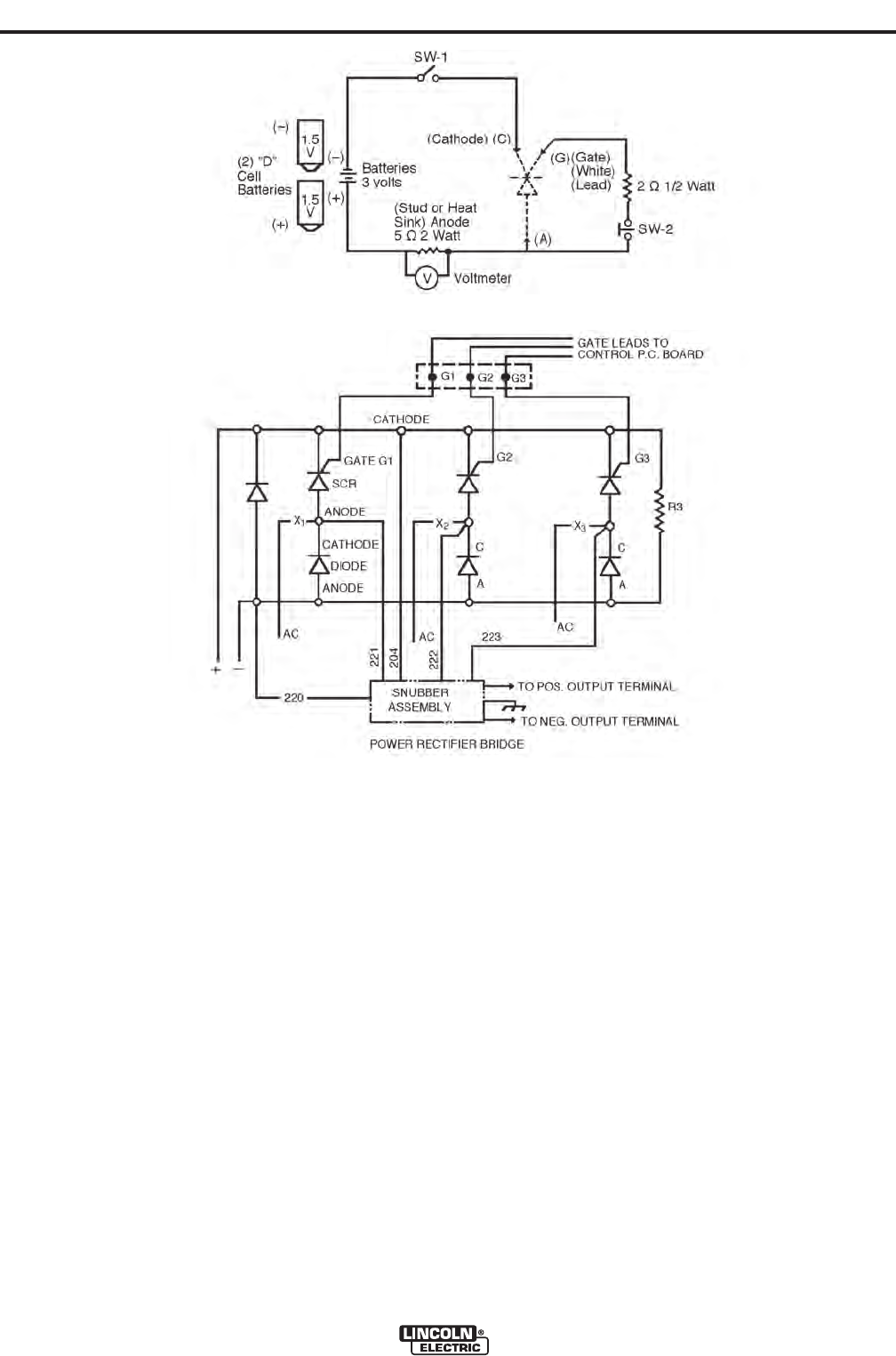
K.POWER SILICON CONTROLLED REC-
TIFIER TEST
The SCR must be mounted in the heat sink when
making this test.
a. Connect the ohmmeter (set to the X10 scale)
leads to the anode and cathode.
b. Reverse the leads of the ohmmeter from Step a.
c. A shorted SCR will indicate zero or an equally
low resistance in one or both directions.
d. Establish the polarity of the ohmmeter. Connect
the positive lead to the gate and the negative
lead to the cathode.
e. An open gate circuit will have an infinite or high
resistance. A good gate circuit will read a low
resistance, but not zero ohms.
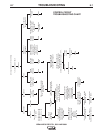
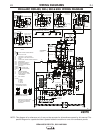
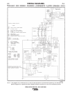
IDEALARC® R3R 375-I, 500-I AND 600-I
DIAGRAM 1
DIAGRAM 2