


A-12
INSTALLATION
POWER WAVE® S350
A-12
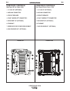
CONTROL CABLE CONNECTIONS
General Guidelines
Genuine Lincoln control cables should be used at all
times (except where noted otherwise). Lincoln cables
are specifically designed for the communication and
power needs of the Power Wave / Power Feed sys-
tems. Most are designed to be connected end to end
for ease of extension. Generally, it is recommended
that the total length not exceed 100ft. (30.5m). The
use of non-standard cables, especially in lengths
greater than 25 feet, can lead to communication prob-
lems (system shutdowns), poor motor acceleration
(poor arc starting), and low wire driving force (wire
feeding problems). Always use the shortest length of
control cable possible, and DO NOT coil excess
cable.
Regarding cable placement, best results will be
obtained when control cables are routed separate
from the weld cables. This minimizes the possibility of
interference between the high currents flowing
through the weld cables, and the low level signals in
the control cables. These recommendations apply to
all communication cables including ArcLink® and
Ethernet connections.
Product specific Installation Instructions
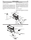
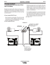
Connection Between Power Source and ArcLink®
Compatible Wirefeeders (K1543, K2683 – ArcLink
Control Cable)
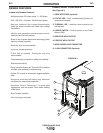
The 5-pin ArcLink control cable connects the power
source to the wire feeder. The control cable consists
of two power leads, one twisted pair for digital com-
munication, and one lead for voltage sensing. The 5-
pin ArcLink connection on the Power Wave S350 is
located on the rear panel above the power cord. The
control cable is keyed and polarized to prevent
improper connection. Best results will be obtained
when control cables are routed separate from the
weld cables, especially in long distance applications.
The recommended combined length of the ArcLink
control cable network should not exceed 200ft.
(61.0m).
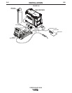
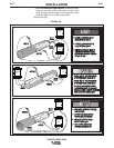
Connection Between Power Source and Ethernet
Networks
The Power Wave S350 is equipped with an IP67 rated
ODVA compliant RJ-45 Ethernet connector, which is
located on the rear panel. All external Ethernet equip-
ment (cables, switches, etc.), as defined by the con-
nection diagrams, must be supplied by the customer.
It is critical that all Ethernet cables external to either a
conduit or an enclosure are solid conductor, shielded
cat 5e cable, with a drain. The drain should be
grounded at the source of transmission. For best
results, route Ethernet cables away from weld cables,
wire drive control cables, or any other current carrying
device that can create a fluctuating magnetic field. For
additional guidelines refer to ISO/IEC 11801. Failure
to follow these recommendations can result in an
Ethernet connection failure during welding.