


PRE-OPERATION SERVICE
READ the engine operating and maintenance instruc-
tions supplied with this machine.
OIL
This unit is supplied from the factory with the engine
crankcase filled with a high quality SAE 10W/30 oil.
This oil should be acceptable for most typical ambient
temperatures. Consult the engine operation manual
for specific engine manufacturer’s recommendations.
Upon receipt of the welder, check the engine dipstick
to be sure the oil is at the “full” mark. DO NOT overfill.
FUEL
Fill the fuel tank with the grade of fuel recommended
in the Engine Operator’s manual. Make sure the fuel
valves on the sediment bowl and the water separator
are in the open positions.
COOLING SYSTEM
The radiator has been filled at the factory with a 50-50
mixture of ethylene glycol antifreeze and water.
Check the radiator level and add a 50-50 solution as
needed (see engine manual or antifreeze container for
alternate antifreeze recommendations).
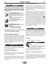
CAUTION
Fuel
can cause fire or explosion.
-
• Stop engine while fueling.
• Do not smoke when fueling.
• Do not overfill tank.
• Keep sparks and flame away from tank.
• Wipe up spilled fuel and allow fumes to clear
before starting engine.
------------------------------------------------------------------------
WARNING
A-3
INSTALLATION
SA-250
A-3
• Design capacity of trailer vs. weight of Lincoln
equipment and likely additional attachments.
• Proper support of, and attachment to, the base of
the welding equipment so there will be no undue
stress to the framework.
• Proper placement of the equipment on the trailer to
ensure stability side to side and front to back when
being moved and when standing by itself while
being operated or serviced.
• Typical conditions of use, i.e., travel speed, rough-
ness of surface on which the trailer will be operat-
ed; environmental conditions, likely maintenance.
• Conformance with federal, state and local laws.
(1)
(1)
Consult applicable federal, state and local laws regarding specific
requirements for use on public highways.
POLARITY CONTROL and CABLE SIZES
With the engine off, connect the electrode and work
cables to the studs located on the fuel tank mounting
rail. (See size recommendations below.) For positive
polarity, connect the electrode cable to the terminal
marked “+”. For Negative polarity, connect the elec-
trode cable to the “-” stud. These connections should
be checked periodically and tightened if necessary.
When welding at a considerable distance from the
welder, be sure you use ample size welding cables.
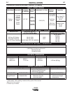
RECOMMENDED COPPER CABLE SIZES
Cables Sizes for Combined Length
of Electrode Plus Work Cable
Amps Duty Cycle Up to 200 ft. 200 to 250 ft.
250 100% 1 1/0
300 60% 1/0 2/0